So your picture:

simulate this circuit – Schematic created using CircuitLab
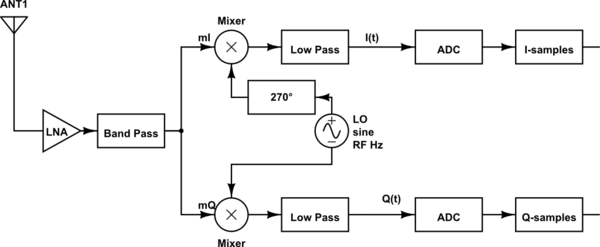
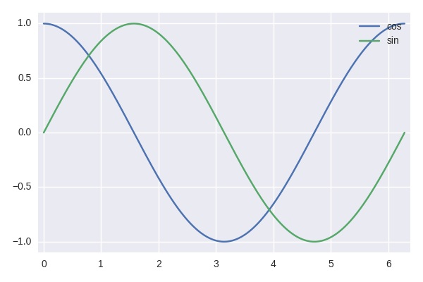
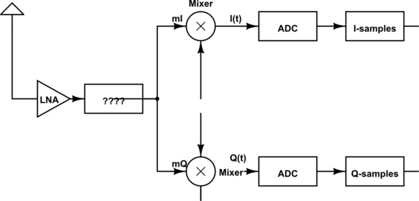
is one of many specific implementations of an SDR; what is implied here is that it is a Direct Conversion Receiver/Quadrature Demodulator, which directly brings down the Antenna signal at $f_{RF}$ to (complex) baseband, using the two mixers fed with a cosine and a sine (notice: same frequency, 90° phase difference). (I know this has confused you in the past: The usage of "Demodulator" here has nothing to do with "AM/PSK/QAM modulation", but with modulation in the mixing sense)
The combination of I and Q signal is called baseband signal. It's called that because it's around 0 Hz.
This means that the signal that was at exactly $f_{RF}$ on the air ends up on exactly 0 Hz after the mixing, and things that were above $f_{RF}$ end up on positive baseband frequencies, whereas things slightly below end up at negative frequencies – for that to work, to mathematically be able to distinguish between positive and negative frequencies, one must declare I and Q parts of a complex baseband signal $s(t) = I(t) + jQ(t)$.
Just like the imaginary axis in the plane of complex numbers is orthogonal to the real axis, the Q axis is orthogonal to the I axis – just that you don't use Pythagoras to prove orthogonality but the infinite integral over the whole space¹.
Regarding your QSD receiver: It's really just a specific special-purpose implementation of the cosine and sine.
Ok, assume you can link the points in time when your ADCs take a sample to your LO frequency. You do so, defining the sampling always to happen exactly when the cosine is 1 or -1 or 0:

so the sine is also either 0, -1 or 1 when that happens.
Hence, you don't actually need the full oscillator shape, just these three values coming in at the right times. And that's exactly what the logic part above does: When the switch is open, the capacitors pull the input of each opamp to zero, when the switch connecting the input signal to inverting input of an opamp it's -1, and if it connects to the positive input, it's +1.
I have to stress this: This is a very special design only useful for the very special case that you only want to sample at an integer factor of the mixing clock, and you have very good control over the phase delay all the connections between components introduce. In general, this design is only used if it is impossible to actually use a fully-fledged oscillator for many reasons.
I've read your other questions on DSP.SE, and this is nothing you'd touch soon, in reality. Yes, there are several ham receivers that work like that beautifully, but to be honest, if I was to demodulate a 10 MHz signal, I'd rather go for the 10 MHz sinusoidal oscillator. Things look different in the multi-GHz case, where getting something to mix reliably is very hard.
¹ Orthogonal are things whose dot product is zero. In geometry, the length of this dot product is the projection of some vector A onto a Vector B, i.e. you build a right(-angled) triangle with A the hypotenuse and B containing one cathete/leg, and then you you drop the perpendicular and measure the length.
If you project the Y axis onto the X axis, you'll see the projection's length is always zero. So X and Y are orthogonal
Now, X and Y are only "normals" under which you "measure" the position of a point in the plane. You take that point, project it onto the X and onto the Y axis, and get the coordinates.
You can do the same for harmonic signals, with another plain: You project that signal $s(t)$ onto $\cos$ and $\sin$ and get the coordinates. In case of your mixer, these would be
$$\begin{align}
i_(t) &= s(t) \cos(2\pi f_{LO} t) \\
q_(t) &= s(t) \sin(2\pi f_{LO} t) \\\\
r(t) &= i(t) + jq(t)
\end{align}$$
If you look at $r(t)$ it describes a function in the complex plane; these are exactly the things you see when you look at one of the classical constellation diagrams!
As a general advice: Try to not mix up too many concepts; take one textbook and read it from front to back, and get a good understanding of what's happening there. Asking about what the parts of Quadrature Demodulator are and how to understand a QSD circuit in the same question is
very symptomatic of someone who tries to understand stuff by googling words – this will confuse you more than it will help, usually, because you don't get a consecutive, logical introduction to stuff, but will be presented with approaches that only make sense if you fully understood the basics.


