How does a noise bridge work? And how can a noise bridge be useful in building, testing, and/or tuning an antenna?
1 Answer
A Noise Bridge is a very useful piece of test kit, often described as a "poor man's antenna analyzer". It's capable of measuring the exact impedance of an antenna, both the resistive and reactive components, something that normally requires a pricey bit of lab equipment.
Unlike an SWR meter, the noise bridge, requires little or no transmitted power applied to the antenna. The SWR meter works by measuring the reflected wave from the antenna back to the transmitter when a transmission is made. But a noise bridge measures the impedance directly allowing an accurate antenna tuning to occur without transmitting, so there is no risk of transmitter damage or QRM on the bands.
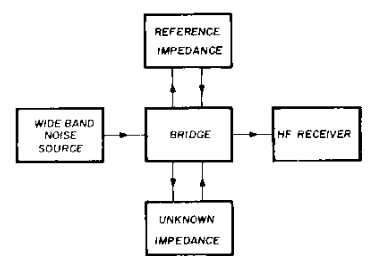
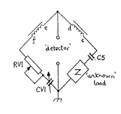
So, how does it work? The bridge has four legs, one is a reference impedance (usually a calibrated variable resistor and a calibrated variable capacitor in series) and the other leg is the unknown impedance to be measured (say, an antenna). A white noise generator injects noise into the circuit that can be monitored by an HF receiver. Then, the circuit is tuned until a null is detected in the receiver, the impedances are now matched and the circuit is in balance.

A schematic look at the bridge:

Pretty nifty, but there are some other things you can do with them:
Trap dipoles: The noise bridge will give a null on each band that the trap dipole resonates. Start with the highest frequency band and measure impedance and reactance as for a normal dipole. Adjust your antenna center section to resonance then repeat on the next lower band and so on. This method can be used on both horizontal and vertical trap antennas.
Beam antenna: Connect the noise bridge to the driven element. Tune your receiver to the operating frequency and read the impedance and reactance. Adjust the element length to bring to resonance.
Testing Baluns: You can't test a Balun or Unun with a VM because they usually have some or all of their legs tied off at DC, so it will read a dead short. Instead, connect your noise bridge to the coax input of the balun. If its a 1:1 balun place a 50 ohm resistor across the output connectors. Now turn on the noise bridge and adjust for a noise null. You should see an impedance of close to 50 ohms and reactance of almost 0.
Tuning the Antenna Tuner: You can set your antenna tuner without using your transmitter. Connect the noise bridge to the transmitter side of the tuner and set the noise bridge controls for X=0 and R=50 and then adjust the tuner for null. Don't leave the noise bridge in place, you'll probably smoke it if you transmit into it.
There are other less common, more technical uses such as determining the inductance of unknown ferrite material, pruning feedlines, etc. Google is your friend here, it's a great piece of test gear to have around and very cheap to build if you don't want to drop $20 or so on a used Palomar R-X or old HeathKit 1422A.
References:
- Palomar R-X Noise Bridge Manual
- JADNDEK Noise Bridge Manual