Since writing this answer, I've learned this explanation isn't entirely accurate. I'm leaving it because it's not entirely wrong, either.
Ultimately, it is impedance mismatch (really, too low an impedance) that damages transmitters. The thing to realize is the impedance seen by the final power transistors in the amplifier (the part that usually breaks) isn't the same impedance at the amplifier's terminals.
The reason is that amplifiers contain filters on their output to filter harmonic suppression, among other things. These filters are designed with the assumption of a 50Ω resistive load. When that assumption holds, the filter presents the design impedance to the finals, which the designer has determined will not smoke the transistors.
When the load is not 50Ω, the design conditions are violated and the impedance presented to the finals could be anything. If you get lucky, it will be a high impedance which just means the amplifier can't deliver its full rated power. If you get unlucky, it's a low impedance which draws too much current and overheats the transistors. It's hard to predict where you will get lucky, and where you will get unlucky without knowing the details of the transmitter's filters. Here's an example from Is there an optimum transmission line length for maximum power transfer?
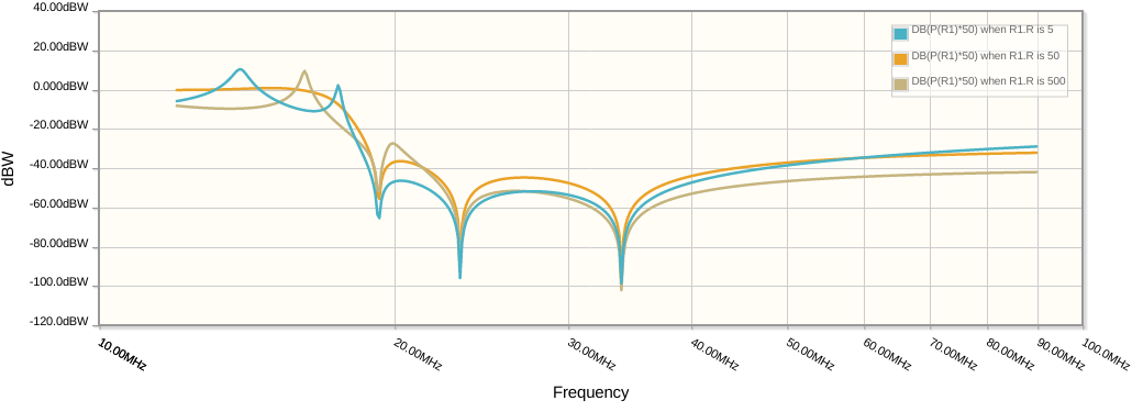
This is a 30/20m filter, so it is intended to pass up to about 14.4 MHz and attenuate all the higher harmonics of that. The orange line shows the case where there's a matched 50Ω load, while the blue and tan lines show 500Ω and 5Ω loads which are two cases of a 10:1 SWR.
Notice how the mismatch introduces peaks in the frequency response. Where these peaks are above the orange line, the amplifier is seeing a lower impedance, thus a higher current and more power. Here's the potential for damage. One of those blue peaks is right at 14 MHz and is about 10dB above the orange line. So on 20 meters, a 100W amplifier is suddenly trying to produce 1000W into a low impedance, which will quickly damage it.
There are any number of impedances which will result in a 10:1 SWR, and depending on the transmission line you might get any of them. I suggest checking out a Smith chart tutorial to get familiar with how this works.
This is why SWR is used to quantify the quality of the match: it is independent of transmission line length. For any given SWR, the height of those peaks in the graph above are about the same, and moving around different impedances with the same SWR just changes where they lie. Since you really don't know where they lie in practice, it's just best to avoid high SWR generally.
