Well, different books / schools use different definitions.
Some authors just copy definitions from others and make mistakes when doing that. In this case, this is pretty likely:
Possibly, someone remembered "hey, shape factor is between the point where there's half the power and -60dB of the power", then when writing down accidentally converted "half the power" to "half the amplitude", and thus used $x [\text{dB}] = 20 \log_{10}(x[\text{linear}])$, as usual for amplitudes, instead of $10\log_{10}$, or just the other way around. The "original" definition might be lost in the sands of time.
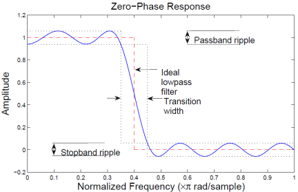
All in all, shape factor is not a measure encountered all that often in modern literature; especially since analog filters typically have to compete with digital ones nowadays, it's become far more usual since about the 80's to refer to transition width or transition band, ie. the bandwidth between edge of passband (i.e. -3dB point, typically), and the point where the filter response crosses it's final/design attenuation the first time:
This figure is taken from the mathworks example on filter design:

I wonder what sense it makes to use a fixed -60dB as reference, anyway – if your filter is designed to have a -60dB attenuation everywhere in the stopband, fine, that makes sense, but you don't generally do that. What if your filter requirements are really just -50dB (and that makes a large difference, both when designing analog and digital filters), and you don't actually care where the attenuation becomes -60dB (or whether that happens at all). Or what if you need a great filter because you're observing something extremely weak and go through lengths and build a -90dB-stopband filter? What use is knowing the ratio of -3dB and -60dB then?
The -60dB measure does make kind of sense in a technological environment where -60dB is actually the maximum physically possible isolation (and that's the case for board-bound electronics, and "free flying low frequency filters", maybe), but that doesn't really apply to all filter designers do nowadays.
I know I'm kind of annoying like that, but if you're really after having good filters: don't design them in the analog domain. It's 2016. Dynamic ranges of ADCs are plenty, by far more than what you need even with strong interferers, together with the fact that Ham bandwidths are negligible small for modern ADC bandwidths. Build an easy filter that makes sure you don't get aliases in your desired bandwidth when sampling with a certain $f_\text{sample}$, then use digital filters (for example: in your PC) to extract the signals you care about – digital filters can be made virtually infinitely steep, and the noise they might contribute due to calculation accuracy is far below anything relevant for almost all use cases, if not totally overspecified.
