1
$\begingroup$

I'm trying to figure out an old handmade antenna I picked up at a swap meet a few years back. It is a dipole (or "doublet"?) that is both made of coax but also fed by a length of built in coax.
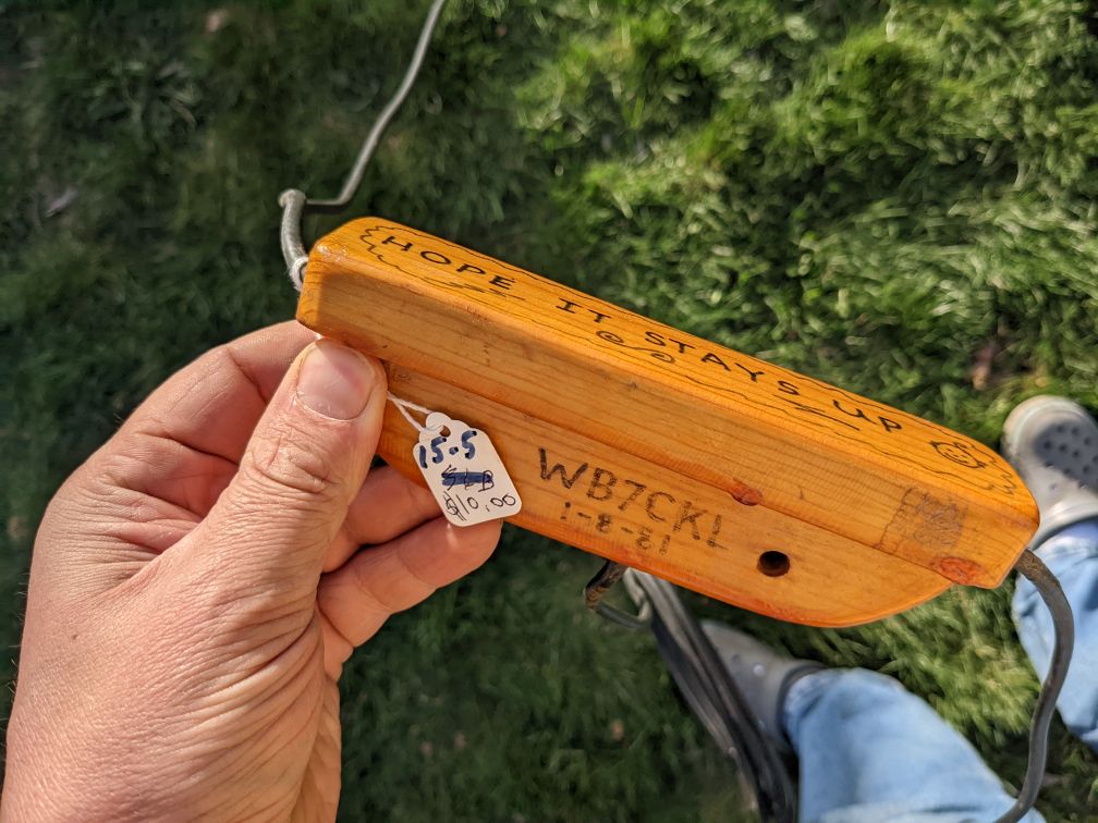
A varnished wooden insulator hand-labelled "HOPE IT STAYS UP" with three different runs of coax coming out of itself. A callsign WB7CKI and a 1-8-81 have also been lettered on

For the elements, it looks like someone has taken a single length of coax approximately 94 feet long and left its center conductor only as (?) a physical support. In the middle of this length, the coax shield was uncovered and a small section cut out, splitting the outer conductor into two separate elements.

This seems like an odd length — as a dipole this might be resonant somewhere in the ballpark of 4.98 MHz, at least using the 468 / frequency rule of thumb. That's getting towards the new 60m band, but there's a 1981 date written on the antenna, I'm assuming to commemorate its construction — long before the 60m band became available in the USA.

So I'm guessing instead this was meant to be some sort of multiband compromise antenna?
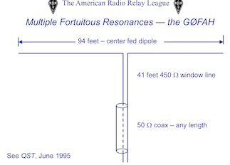
Part of slide "Multiple Fortuitous Resonances" showing schematic of G0FAH antenna

In fact the "Five Bands, No Tuner" G0FAH antenna described within e.g. http://n7twt.net/Antennas/9506059%20Five%20Bands,%20No%20Tuner.pdf (labelled "June 1995 QST Volume 79, Number 6") and also found on page 32 of http://www.hamclass.net/ranv/pres/HC16MultAnt.pdf seems like one possible candidate — except…

Whereas the G0FAH and most other "wrong sized" doublets seem to be fed with balanced 450-Ω ladder line, the antenna I "inherited" was fed with unbalanced 50Ω coax soldered directly on the feedpoint! [Also the G0FAH was apparently published 1995 but this antenna might have been built in 1981 already…]
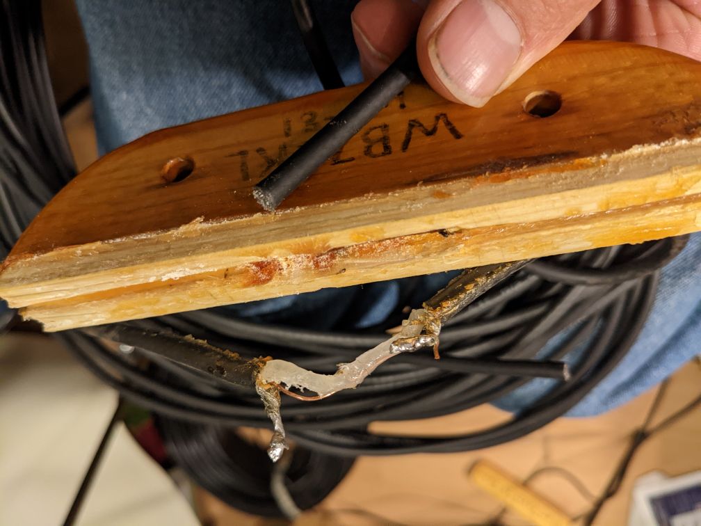
Varnished wooden insulator pulled apart to reveal cut-apart coax

[In the picture above, I've already disassembled it for troubleshooting, and chopped the end of the feedline clean. Originally it connected via each of the two solder blobs remaining on the lower coax.]

Is this any sort of known antenna design? Might its construction be improved by at least a balun/choke at the feedpoint, or is it maybe a lost cause without the proper length of balanced line to serve as a transformer section?

Some more precise lengths in case it's useful:

  • each leg of the dipole reads as 14.26m at 70% velocity factor
  • the feedline coax read as 6.23m, again assuming 70% velocity factor

(The coax is labelled as 58/U which I see is spec'ed to be 66% VF, so the numbers above might be a bit off of the physical length.)

Here's a quick-and-dirty VNA view of the antenna, before I took it apart, seen through the built-in feedline. Note that the trace was "flakey" due to what I think was a short within the feedpoint — the resonant dips would appear and disappear with the breeze:
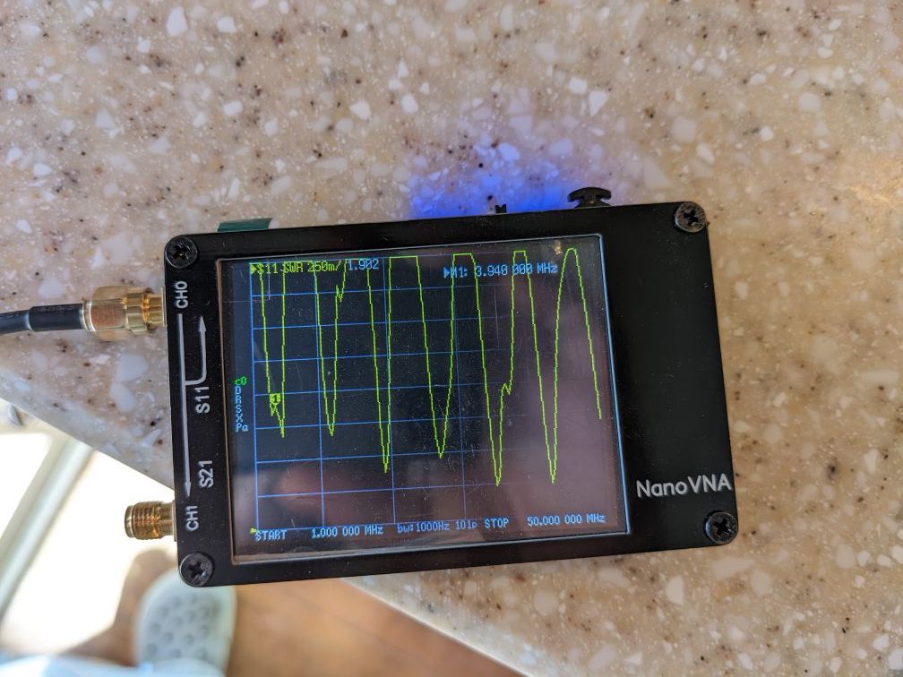
Cell phone photo of a NanoVNA with a marker around 3.5-something MHz and a number of other lower SWR dips at frequencies up through the edge of the graph at 50 MHz

$\endgroup$
3
  • $\begingroup$ Looks like the ZS6BKW dates to at least the mid-1980's and has a similar "random length": ni4l.com/… — but again, that design uses a ladderline transformer section. $\endgroup$ Commented May 3, 2022 at 5:58
  • $\begingroup$ More history on the ZS6BKW: web.archive.org/web/20161216143451/http://ars.nc4fb.org/zs6bkw/… $\endgroup$ Commented May 3, 2022 at 6:00
  • $\begingroup$ Can you sketch the arrangement of coax, position of cuts in the braid, and how it's fed? Your description isn't crystal clear. Are the ends of the coax open or short circuited? $\endgroup$
    – tomnexus
    Commented May 16, 2022 at 4:36

2 Answers 2

2
$\begingroup$

From your description, it looks like a form of a coaxial dipole or coaxial folded dipole, also called a "bazooka". The bazooka was developed by the staff at M.I.T. (Massachusetts Institute of Technology) for radar use, and featured later in QST Magazine published by the ARRL (July 1968).

See: QST July, 1968, page 38, via World Radio History:

https://worldradiohistory.com/QST.htm

The design was adapted for the ham and shortwave bands. The 94 ft. element section may only have been part of the radiating element. There may have been extensions off the ends, tuning it for 80 meters.

See:

http://webclass.org/k5ijb/antennas/Bazooka-dipole-antenna.htm

Google "coaxial dipole" for other info.

$\endgroup$
2
  • $\begingroup$ Thanks, but the far ends of the coax used as the antenna elements are not soldered and no evidence they ever were. I'm less intrigued by the use of coax for the elements as I am by the use of coax for the feeder. $\endgroup$ Commented May 4, 2022 at 18:05
  • $\begingroup$ Many antenna designs use a segment of coax between the 52 ohm transmitter feedline and the (larger impedance) antenna feed point to perform a homebrew impedance transformation between the two. Perhaps this is why? $\endgroup$ Commented May 4, 2022 at 19:12
0
$\begingroup$

Nate.

Just because someone made an antenna years ago with a ham call sign on it doesn't mean that it's a proper or valid design that actually worked.

This could just have been an experiment or a misguided attempt at antenna construction, or it could have been made by a child as a project at a scout group, or by someone who wasn't that bright or really drunk.

The fact that it has a ham radio call sign actually on it is probably not a good sign, it's a bit like in grade 2 when your mum put your name on your lunchbox just in case you lost it.

I wouldn't read too much into the design of this antenna.

Hope that helps !

$\endgroup$
2
  • 1
    $\begingroup$ I guess? Putting a callsign and a "Hope it stays up" label is exactly the sort of humour I'd expect from a ham. No pun intended. As you say, it may be a poor design or construction, but I think we can accept this for what it is: a homebrew antenna of some pedigree made or designed by WB7CKL. $\endgroup$
    – user21417
    Commented May 16, 2022 at 12:27
  • $\begingroup$ Yep, but figured I'd ask if it seemed familiar to anyone before just writing it off. I did end up scrapping it after all regardless — the dielectric in the open center portion was ruined to the point where the outer shield elements were shorting out onto it and after some modest effort to fix it, I gave up and just chopped up the good sections of the coax for reuse in whatever future project. $\endgroup$ Commented May 16, 2022 at 20:34

You must log in to answer this question.

Not the answer you're looking for? Browse other questions tagged .