1
$\begingroup$

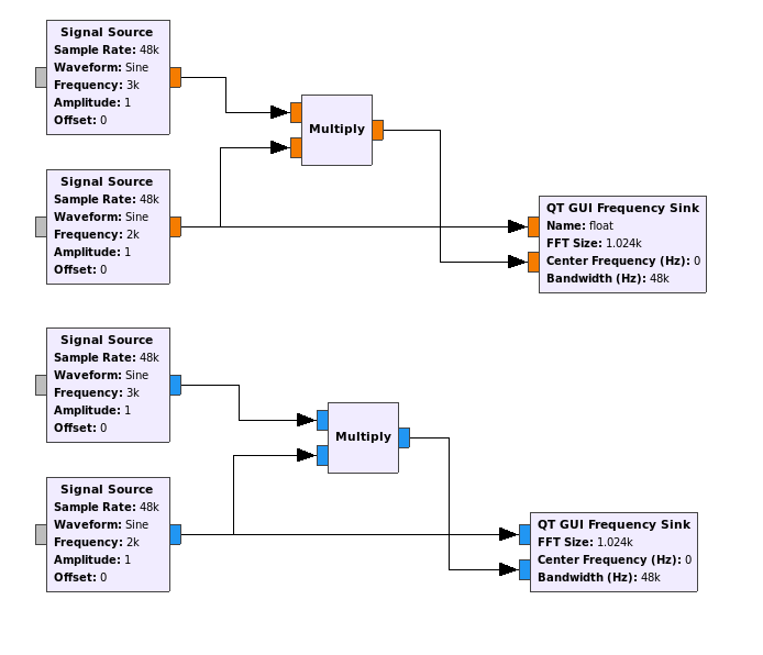
Construct 2 similar flow graph in Gnuradio,just different with data type.

enter image description here

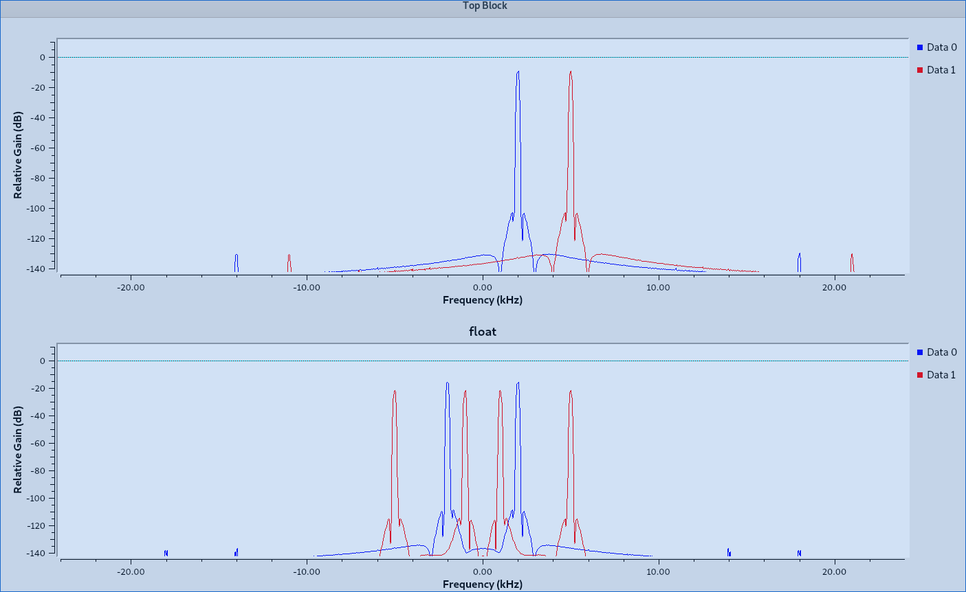
complex type data has a correct result.But float type data output 3 peaks,I don't understand.

enter image description here

What cause multiply has difference result between float and complex signal?

$\endgroup$
1
  • $\begingroup$ "but float type data output 3 peaks" I count 4, not 3. $\endgroup$ Commented Sep 3, 2021 at 2:37

4 Answers 4

4
$\begingroup$

This is a consequence of what was discussed in your previous question, that any real-valued function like $\sin(\omega t)$ consists of both positive and negative frequencies.

Multiplying by a complex exponential $e^{i\omega t}$ simply shifts frequency by $\omega$. There are many ways to show this, one way is to simply look it up in a table of Fourier transforms, where you will find the Fourier transform of

$$ f(x) e^{iax} $$

is

$$ \hat f(\omega -a) $$

But multiplying a function by $\sin(ax)$:

$$ f(x) \sin(ax) $$

is

$$ \frac {{\hat {f}}(\omega -a)-{\hat {f}}(\omega +a)}{2i} $$

This equation is the basis of a frequency mixer which produces new signals at the sum and difference frequencies.

In your example with complex-valued blocks, you begin with a complex exponential which has a signal at just one frequency. Then you multiply that by another complex exponential, leaving you with still just one frequency, but shifted.

In your example with real-valued blocks, your first sinusoid begins with signals at two frequencies. Again, any real-valued function must have both positive and negative frequencies. When you multiply that by another sinusoid, you are both shifting those two frequencies you started with up (with the positive frequency) and down (with the negative frequency) present in your second signal block. The end result is the two frequencies are split into four.

This complication of creating sum and difference frequencies is a design challenge in superheterodyne receivers. Since a typical superhet receiver operates on a function represented by a voltage which must be real, every time the receiver employs a mixer to shift frequency up or down there are two frequencies in the input which map to the target output frequency. Therefore, filtering must be employed to ensure there are no signals at this image frequency which would otherwise create interference.

This can be avoided when signals can be complex. In analog designs it's difficult to do this accurately, but digitally it's no problem, and this is part of why much digital signal processing is done with complex values, rather than real values.
$\endgroup$
0
4
$\begingroup$

That's just the math behind it – everything is alright with these results!

You need to write down the formula of the real-valued $\sin(t)$ in terms of $e^{j2\pi t}$ and $e^{-j2\pi t}$, and you'll see that, as shown in your plots, the real-valued harmonic oscillations have a positive and a negative frequency component – so multiplying two of these yields four components.

This isn't really a programming or even a DSP problem – you just have to be precise with the math.

$\endgroup$
1
  • $\begingroup$ by the way, this has nothing to do with this particular question, but you're using an outdated version of GNU Radio. $\endgroup$ Commented Sep 2, 2021 at 22:33
1
$\begingroup$

If I understand your question correctly, the issue is that you have one graph producing a complex output of an FFT and the other producing a floating point output from an FFT.

When you produce an FFT from complex data using a floating point output, you will find that the signal is reflected across the y axis at zero. This is because the floating point version does not capture the phase angles since they are in the complex plane.

There is a very good discussion of this here.

$\endgroup$
1
$\begingroup$

A real-valued multiply is the same as an AM modulation, where the result includes both upper and lower sidebands. (Similar to the spectrum of an AM radio station on an SDR waterfall.)

A complex-valued multiply is more like an SSB modulation (plus carrier, depending on modulator depth and offset). So you only get one sideband, upper sideband if the modulator is a positive complex exponential, lower side-band if the modulator is a negative exponential.

If you look at the signal from an SSB transmitter, you might only see a weak opposite sideband signal if the transmitter is poorly filtered, (non-linear) distorting, and/or splattering spurious stuff.

Works the same way with the math equations as with actual radio modulation circuits (tube, transistor, or diode) (single channel heterodyne vs. IQ modulation).

Learning about complex numbers and how they add and multiply also helps.

$\endgroup$

You must log in to answer this question.

Not the answer you're looking for? Browse other questions tagged .