The Question addresses a persistent confusion which is widespread especially in the ham radio community and can be tracked down to some published material (here no names!) and has survived since many years.
However, a clarification can be straightforward and does not require complicated math. This answer starts from the “Total Feedline Loss” equation that had been derived in a previous thread and often appears in ham radio publications:

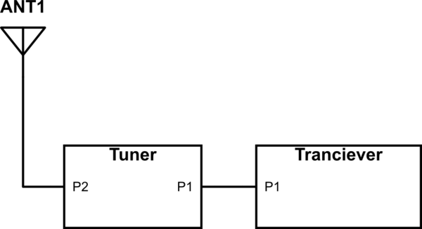
Behind this correct loss equation there are crucial assumptions for its validity, including (1) The characteristic impedance of the feedline (e.g., coax) must be a real (not complex) value, which is reasonably satisfied at higher RF frequencies (but probably not for 40m, 80m, 160m bands for which additionally the physical line-length may become much shorter than the electrical wavelength on the line). – The second (2) assumption is much more relevant in the context of this thread: A (lossless) tuner is assumed at the input of the feedline. This tuner performs complex conjugate impedance matching such that the transceiver can feed its maximum available power into the feedline.
Because of reflections at the far-end, e.g., at the feed-point of an antenna, a fraction of the transmit power (in terms of voltage/current waves) returns to the input of the feedline. There, the returning waves feel the output impedance of the matching network (tuner). This impedance is the complex conjugate of the feedline input impedance; it determines, together with the feedline characteristic impedance (e.g., 50Ω coax), the extent of reflection expressed by the (complex) reflection coefficient. Note, there is no total re-reflection. Such total re-reflection would require an infinite, or a zero, or a pure reactance impedance; all these cases do not apply here, regardless of the tuner being a lossless LC network which transforms the output impedance of the transceiver (e.g., 50Ω).
However, the above “Total Feedline Loss” equation is frequently derived based upon a perception of total re-reflection and results from an infinite geometric series. And, indeed, the equation is correct! So, what is going on? Well, applying the idea of total re-reflection is a somewhat dirty way to arrive at a correct equation. The end-result for the total loss is the same, regardless of either applying the fake of total re-reflection, or the true physics of the actual phase-accurate superposition of partially reflected voltage/current signal components and applying the true reflection coefficient. Although the end-result is the same, the bouncing-steps during the transient period are quite different. The above “Total Feedline Loss” equation is valid, although its derivation is very often flawed, which leads to confusion, paradoxes and such concerns like expressed in the Question.
 (Credit: Cartoon by Tayfun Agül)
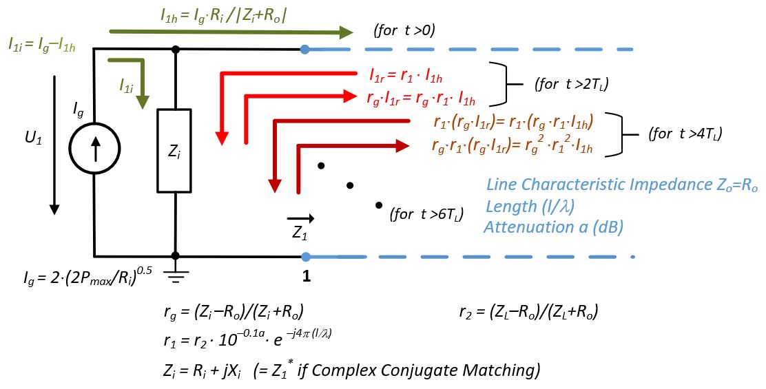
Under the condition of complex conjugate matching, the “Total Feedline Loss” formula does not show explicitly the reflection coefficient that is relevant for the re-reflection of voltage/current signal components that return to the feedline input.
Of course, when arriving at the feedline input, the same partial re-reflection applies not only to a returning fraction of the transmit signal, but equally also to any receive signal; there is no difference, assuming the Tx and Rx signals are similar in frequency, implying similar reflection coefficients.
The following experiment illustrates the difference in bouncing-steps. We assume a system that is easy to calculate (and easy to measure!). A lossy 50Ω coax is terminated into an ohmic resistor of 290Ω. This load resistor implies that half of the forward power is reflected at the load,
$$|Γ|^2=|(290-50)/(290+50)|^{2}=0.5$$
The coax line attenuation is 3dB (i.e., L=0.5). The coax length is a multiple of (λ/2); such length-choice avoids here the hassle of complex values and implies that the feedline input impedance is also ohmic; it is 104.9Ω (obtained by calculation, or Smith Chart etc.). We assume a (lossless) LC tuner that matches the feedline input impedance of 104.9Ω to the transceiver output impedance (say, 50Ω). Thus, the tuner output impedance (seen when looking from the feedline into the tuner) is adjusted to be also 104.9Ω. The signal components that return to the feedline input, experience reflection with a coefficient $$Γ_s=(104.9–50)/(104.9+50)=0.35$$ or $$|Γ_s|^2=0.13$$ (instead of any faked $|Γ_s|^2=1$).
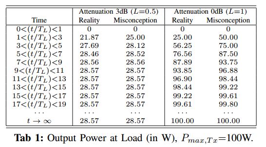
Inserting the values into the “Total Feedline Loss” equation gives a system loss of 5.44dB (or linear 0.2857). If the maximum available power from the transceiver is 100W then – after the bouncing has finished – a steady power of 28.57W is delivered to the load resistor.
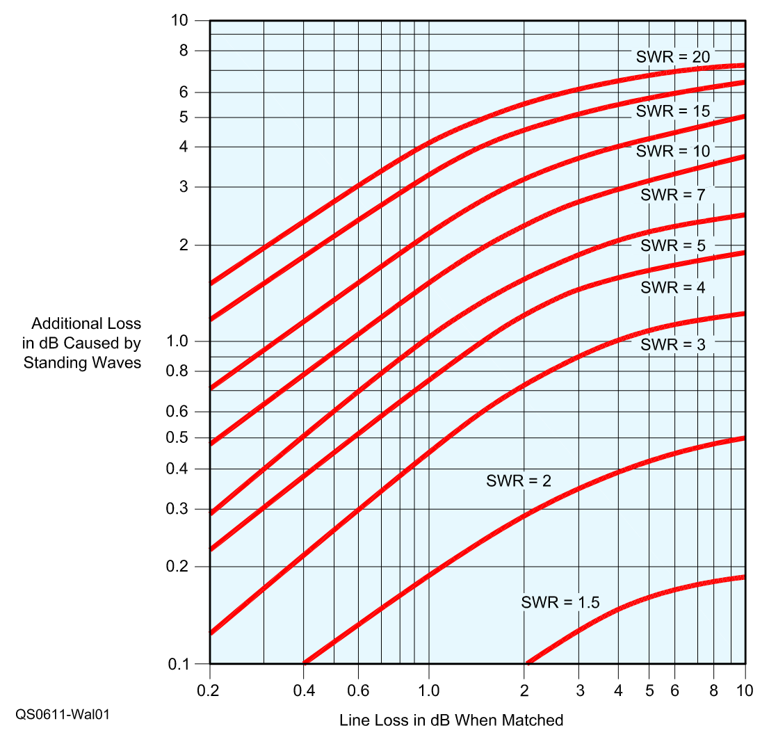
Connecting to the diagram in the Question, our system loss of 5.44dB includes the 3dB “Line Loss in dB When Matched” plus 2.44dB “Additional Loss in dB Caused by Standing Waves”; note our SWR is here (290/50) =5.8. The transceiver pumps 100W into the feedline. Part of this power (28.57W) is dissipated in the load at the end of the feedline; the remaining part (71.43W) is dissipated in the feedline which is quite lossy (here 3dB, means 50W matched line loss plus 21.43W additional loss due to SWR). There is no power going back into the transceiver because it is (via a (lossless) tuner) impedance-matched to the input impedance of the feedline. All power of 100W remains, and is dissipated, inside the system of feedline plus connected load. This applies regardless of the actual reflection coefficient (here $Γ_s=0.35$) being different from 1.
@sm5bsz (comment on separate Answer): “… regarding the diagram … It shows the fraction of the power sent into the cable that is converted
to heat. (The rest is delivered to the antenna.)” (quote) That is a
misleading statement. The curves in the diagram show only the
loss due to SWR. The total loss (and thus the total power converted to
heat) is higher by the added Matched Line Loss of the cable on its
own.
For comparison, we also consider the case of a lossless line (L=1). The “Total Feedline Loss” becomes 0dB, regardless of mismatch at the load side. The input impedance of the feedline is now identical to the load resistor (remember the line being a (λ/2)-line), and the tuner is adjusted for an output impedance of also 290Ω. The reflection coefficient at TL input becomes $Γ_{in}=Γ=0.71$. The power delivered to the load resistor – after the bouncing has finished – equals now the maximum available power of 100W from the transceiver.
The following table shows the bouncing for the two cases of line attenuations and for the “Reality” of true partial re-reflection, and for the “Misconception” of total re-reflection. $T_L$ is the one-way delay time of the coax. The lower the line loss (in dB), the more evident become the transient discrepancies, and the bouncing will take longer until the steady state is reached.
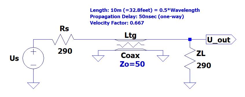
The “Reality” cases can be verified by measurements and by simple simulations; here is a simulation schematic (LTspice) for the discussed second case of 0dB feedline loss. The voltage $Us$ is scaled accordingly for a maximum source power of 100W.
More general: If the condition of complex conjugate impedance matching (e.g., by a tuner) is satisfied at the input of the transmission line, also the reflection coefficients $\Gamma_{in}$ at TL input and $\Gamma_{s}$ of the source (or tuner output) are complex conjugate to each other,
$$\Gamma_{s} = \Gamma_{in}^{\ ^{*}}$$
This implies
$$|\Gamma_{s}| = |\Gamma_{in}| = L\cdot |\Gamma |$$
where $\Gamma$ is the reflection coefficient at the load, and $L$ (linear) is the Matched Line Loss. Therefore, we can rewrite the formula for the “Total Feedline Loss” as function of $|\Gamma_{s}|$ explicitly:
$$
-10\log \left( L\frac{1-|\Gamma |^{2}}{1-L^{2}|\Gamma |^{2}}\right) =
-10\log \left( L\frac{1-(|\Gamma_{s}|/L)^{2}}{1-|\Gamma_{s}|^{2}}\right)
$$
Obviously, the complex conjugate matching at the TL input (e.g., by a tuner) does not imply $|\Gamma_{s}|=1$.
If no complex conjugate matching applies at the transmission line input, the “Total Feedline Loss” formula (in dB) becomes
$$
-10\log\left( L\cdot\frac{1-|\Gamma |^{2}}{1-L^{2}|\Gamma |^{2}} \cdot
\frac{4R_{s}R_{in}}{|Z_{s}+Z_{in}|^{2}}
\right)
$$
where the (complex) $Z_{s}=R_{s}+jX_{s}$ is the (Thévenin equivalent) source output impedance at the given operating point; and the (complex) $Z_{in}=R_{in}+jX_{in}$ is the input impedance of the transmission line. – If the two impedances are complex conjugate to each other (tuner case), $Z_{s}=Z_{in}^{\ ^{*}}$, the corresponding last quotient in the above total loss formula becomes 1. Note the characteristic impedance, $Z_o$, of the transmission line is still assumed to be a real value. (Obtaining/measuring the two impedances $Z_{s}$ and $Z_{in}$ is perhaps beyond the scope of this Question.)
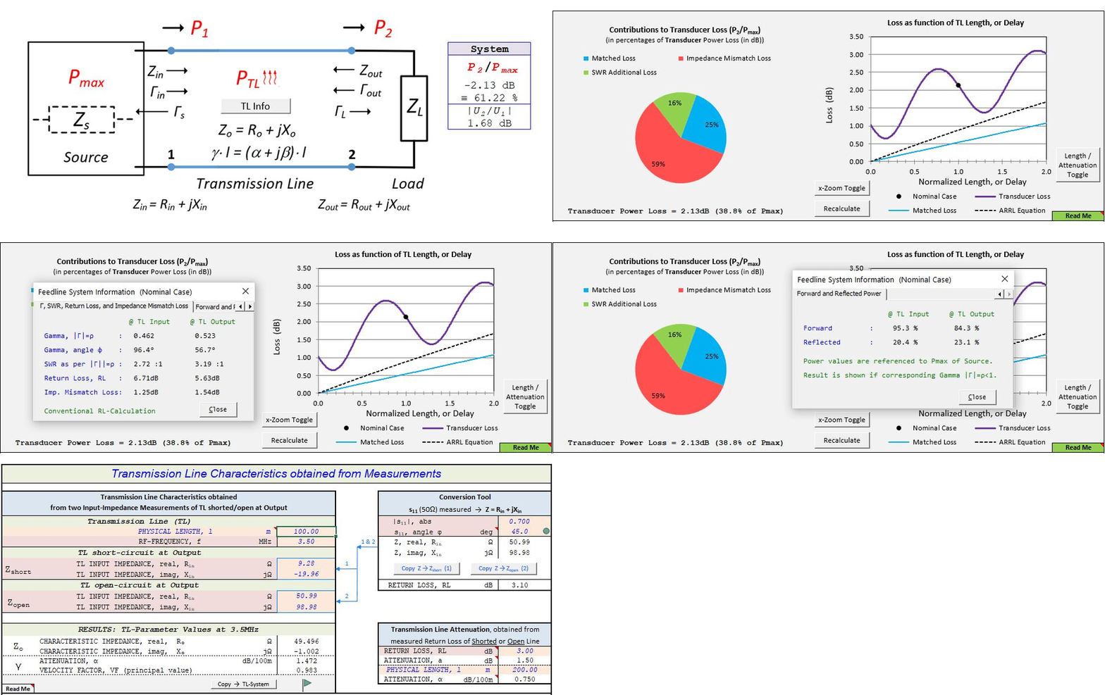
An Excel tool downloadable at www.rfclb.space/#TLine does all calculation and allows for “Total Feedline Loss” trade-offs considering different approaches of impedance matching by a tuner (far-end; near-end; complex conjugate matching; zero-reflection), or tuning by simple feedline extension; the tool covers also the case of complex characteristic impedance of the transmission line.
Conclusion answering to the 3-fold Question:
(1) The diagram in the Question and the “Total Feedline Loss” formula are correct; both are based upon the condition of complex conjugate matching (CCM) at the feedline input, achievable for instance by a lossless tuner. This principle applies regardless of (modern or heritage) technology used in the transceiver. – (2) Whether a tuner is required depends on the situation and the question to what extend the CCM condition can be, or is already, achieved by the feedline system, including the transceiver, i.e., w/o insertion of a tuner. – (3) No, the tuner cannot distinguish between (a) transmit signal components that, due to reflection, might return to the feedline input; and (b) any receive signal. Partial re-reflection applies for both signal components, regardless of being Tx or Rx related. The CCM condition does NOT imply any necessity of “total re-reflection” with $|Γ_s|=1$.
$$ $$
PS:
For those who wish to further dive into the nitty-gritty-down-in-the-weeds technical details, here is a diagram for a re-reflection assessment at the feedline input.
