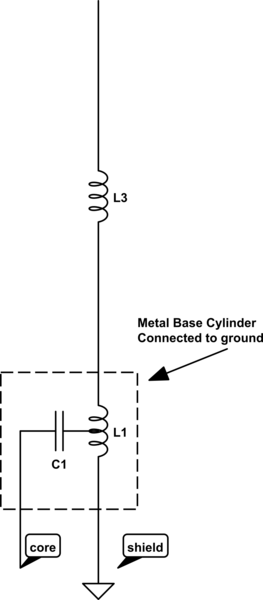
I have several ground independent dual band antenna of different makes, but they all have the same type of matching circuit to make them ground independent / radial-less and match say 5/8 elements, something like pictured below. Ive been trying to model this in 4nec2 to get a similar result to what my nano vna shows, but not able to get there. Not sure this is the right software or approach to use. If its possible id like some tips, or advice on more suitable software.
-
1$\begingroup$ Please, tell us what you want to accomplish with the software. I assume you want to establish values for C1 and L1, but it's not clear from your question. Thanks. $\endgroup$– Brian K1LICommented Feb 20, 2021 at 10:42
-
$\begingroup$ Hi @BrianK1LI, I can gain the values for the existing components from having dissembled these antennas. But im trying to retune/mod them for slightly higher frequency use, Ive experimented with changing the antenna i have with mixed results, so looking to understand the workings and make potential variations easier and quicker, and/or even design one from scratch. $\endgroup$– Hayden ThringCommented Feb 20, 2021 at 10:54
1 Answer
Here's an example of what you could do with EZNEC+, a graphical user interface to the NEC2 computing engine. Note that the values below are not meant to represent a working design, they only serve to illustrate one use of the program. It may be possible to accomplish the same results with other (and free) software.
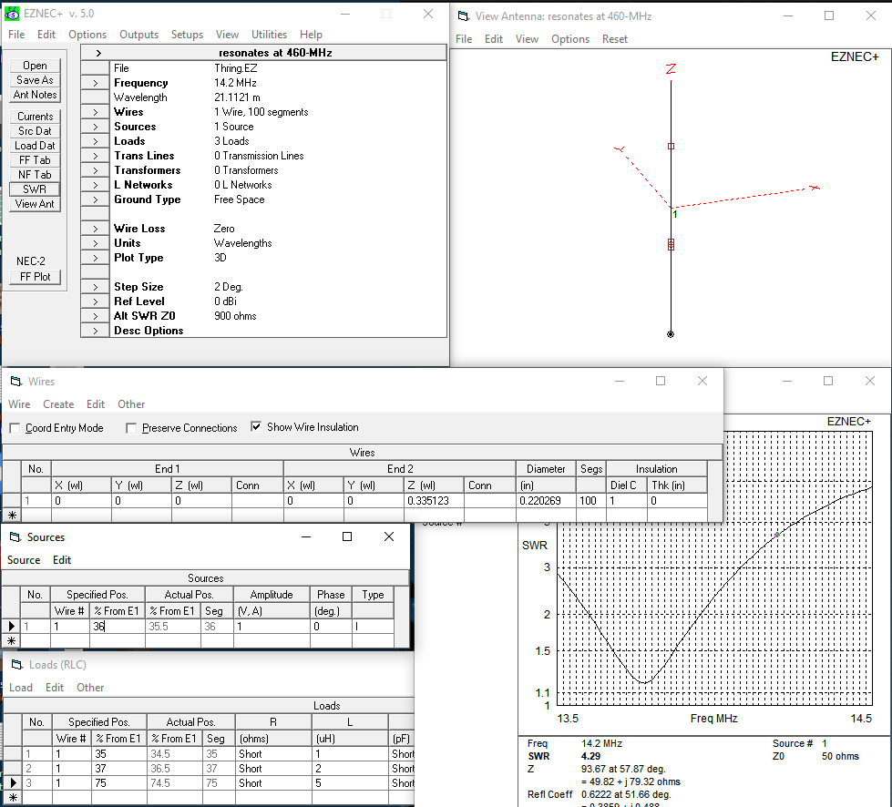
The "Wires" pane shows that the radiator is about 1/3-$\lambda$ long on 14.2-MHz. The square markers on the radiator are "loads," while the circle on the radiator is the "source."
The "Loads" pane shows:
- The tapped coil is split into 1-$\mu$H and 2-$\mu$H sections placed towards the bottom of the radiator
- A 5-$\mu$H loading coil is placed near the middle of the upper section.
The "Sources" pane shows that a current source is placed between the two sides of the tapped feedpoint coil.
The SWR plot bottoms out at 13.85-MHz with an impedance of 42.5+j1.7$\Omega$, but we want to operate the antenna on the 20m band. The impedance is 49.8+j79$\Omega$ at 14.2-MHz; the 79$\Omega$ of inductive reactance could be canceled with a series-connected 142-pF capacitor, as shown in the OP's drawing, to deliver a near-perfect match.
-
$\begingroup$ But you are feeding it 36% from the end, it is no longer an end fed, as so you have created a large 'ground' radial that doesnt exist normally, also it would be better if your loads panel was all visible $\endgroup$ Commented Feb 20, 2021 at 23:10

