Given a dipole approximately 0.48 wavelengths long, such that when fed in the center the feedpoint impedance has zero reactance, how does the complex impedance change as the feedpoint is moved away from the center?
2 Answers
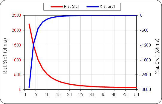
Using a NEC-2 model, here's how R and X of a free-space 20-meter dipole made from #14 copper wire vary with feedpoint position (50 = center fed; 0 = end fed):
-
$\begingroup$ This graph answers the question exactly in my opinion because it shows the change in reactance which results as the feed point is moved away from the center such that the current reflected from the ends of the antenna is no longer in phase with the applied voltage because the antenna elements are no longer 1/4 wave length. In this case the antenna is no longer resonant, even though it would be resonant when fed from the center. $\endgroup$– AndrewCommented Jun 20, 2020 at 1:47
-
$\begingroup$ So the term "öff center fed resonant dipole" would be self contradicting, and the term "center fed half wave dipole" inherently includes the premise that the antenna is resonant because a center fed dipole is resonant when it's electrical length is half that of the frequency of operation. $\endgroup$– AndrewCommented Jun 20, 2020 at 1:49
-
$\begingroup$ When the feed point remains fixed in the center, can there be a graph of the phase relationship in time between the voltage and current at the points between the center and the ends of the antenna which also shows the values of reactance ? as per this question :ham.stackexchange.com/questions/16874/… $\endgroup$– AndrewCommented Jun 20, 2020 at 1:50
-
2$\begingroup$ Note that the reactance remains close to zero - less than 10% of the resistance - for feedpoint offsets as great as 30% from the center (20 on the x-axis of the graph), indicating that the resonance condition is nearly met for a wide range of offsets. $\endgroup$ Commented Jun 20, 2020 at 9:16
-
$\begingroup$ Hi Brian i have one of these at home and yes it does have a low swr on many of the HF bands, it actually works very well. $\endgroup$– AndrewCommented Jun 20, 2020 at 11:01
Both the real and the imaginary terms of the complex impedance across the feedpoint terminals will change as the feedpoint moves away from the electrical center of the antenna.
As an example, a NEC4.2 calculation for a nominally 1/2 wavelength radiator in free space when the feedpoint is located 0.05 wavelengths from one end is about 1340 -j1100 Ω.
A center-fed, nominally 1/2-wavelength dipole at first self-resonance in free space has a feedpoint impedance of about 65 ±j0 Ω.
-
1$\begingroup$ Could you, please, add a graph of R and X vs. position of the feedpoint? $\endgroup$ Commented Jun 15, 2020 at 13:03
-
$\begingroup$ Hopefully someone with AutoEZ will step up to your request (I don't have it). $\endgroup$ Commented Jun 15, 2020 at 14:56
