Judging from posts on the Internet, this belief commonly is considered to be valid. But what is the correct answer?
1 Answer
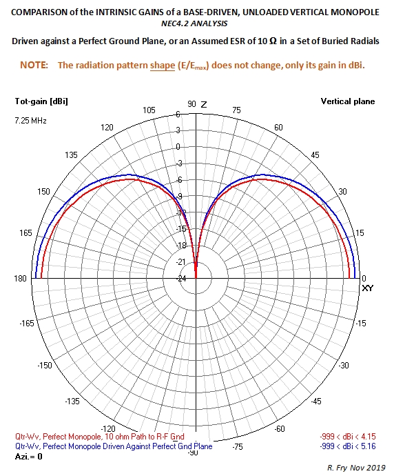
The NEC4.2 analysis below compares the intrinsic fields/gains of the same monopole for the definitions and conditions shown in that graphic.
Note that the monopole having a 10 Ω path connecting it to the ground plane does not display zero gain in the horizontal plane, then gradually rising to more positive values for greater elevation angles above the horizontal — as is shown by a NEC "far-field" analysis. The analysis below shows that the greatest field/gain reduction actually "launched" by that monopole using the 10 Ω path to r-f ground is about 1 dB (in the horizontal plane), relative to using a perfect ground.
Propagation losses beyond a few wavelengths away from these monopoles affect their intrinsic radiation patterns. However when an imperfect ground plane is present, the losses existing beyond that radius distance produce more attenuation for low-angle, radiated fields.
It is this phenomenon that produces the zero and relatively low-amplitude, low elevation angle fields/gains shown by a far-field analysis using NEC (MoM software), from vertical monopoles using imperfect ground planes.
However that doesn't mean that those fields/gains first launched by a vertical monopole using imperfect ground planes did not have much higher values closer to the antenna site.
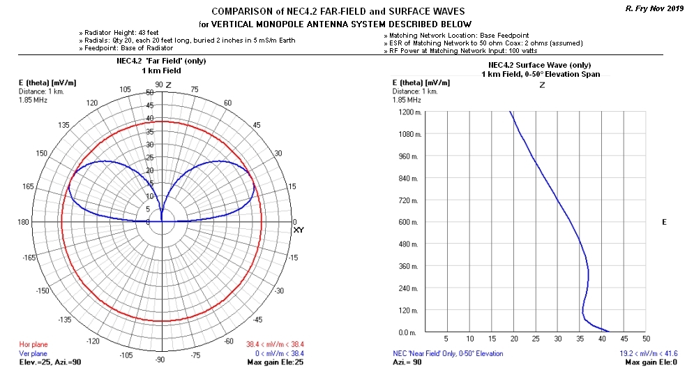
In response to the comments of tomnexus, this edit to my answer adds a new graphic (below), which better illustrates these issues and observations.
Amateur radio operators tend to use the NEC-calculated far-field analysis almost exclusively. However the far field as defined in antenna engineering textbooks begins at a distance of about 2L²/λ meters [L = Radiator Length(Height), in meters; λ = wavelength, in meters].
Note that at the distance of 1 kilometer specified for the e-fields of these NEC calculations, both the far-field and the surface wave values lie in far-field of that radiator.
Using only the NEC far-field pattern to analyze the performance of a vertical monopole antenna system driven against a lossy ground plane can lead to a belief that it has zero radiation in the horizontal plane, and not much more than zero at very low elevation angles.
However that is not always the case, when NEC analyzes the surface wave at ranges within distances of 30 miles or even more from the antenna site (depending on radiated power, frequency, ground plane conductivity etc).
Added November 29, 2019
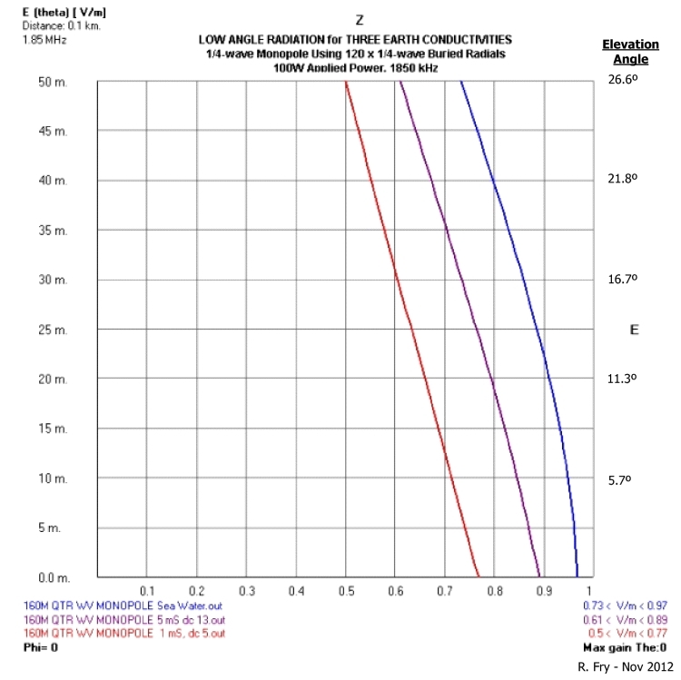
Below is an expansion of my answer to address the concept that the radiation pattern of a vertical monopole requires a circular ground plane having a radius of some 10 to 100 wavelengths in order to reach its final form.
The graphic below shows the radiated fields of a vertical monopole for the conditions shown in the graphic, calculated using NEC4.2. Elevation AGL is shown on the left Y axis; field intensity 0.1 km from the radiator vs. elevation angle are shown by the X axis and the right Y axis.
Observations, for these conditions:
» The fields for Earth conductivities ranging from sea water (5,000 mS/m) to very poor (1 mS/m) all have nearly the same relative values (E/Emax)
» All of these radiated fields are maximum in the horizontal plane
» These radiation patterns did not require "10 to 100 wavelengths" to form; the 0.1 km horizontal distance used in this analysis is only 0.617 wavelengths away from the radiator
» Low values of Earth conductivity do not produce zero v-pol radiation in the horizontal plane, as shown by a NEC far-field (only) analysis
For reference, the field at 0.1 km radiated by this transmit/antenna system using a perfect ground plane is 0.992 V/m, an improvement of only 0.19 dB when compared to sea water.
 ]3
]3
-
$\begingroup$ Your text is correct but as you say the simulation is only of a perfect, infinite ground. Try the Sommerfeld-Norton ground in NEC, GN type 2. It more accurately models the currents in the antenna itself (near field interaction with the ground, more important with horizontal antennas) and also the radiation patterns by far-field approximation using reflection. If you use this you'll see expected null on the horizon, and a low angle of radiation. $\endgroup$– tomnexusCommented Nov 4, 2019 at 19:33
-
$\begingroup$ However the "expected null" that appears in the NEC far-field analysis does not appear fairly close to the antenna site when the surface wave is included in that analysis. This leads some observers to believe that no low-angle radiation ever exists from a vertical monopole antenna system. If that was true, MW AM broadcast stations would have fewer daytime listeners than they have now. $\endgroup$ Commented Nov 4, 2019 at 21:50
-
$\begingroup$ True, but you need to define Low Angle Radiation precisely. On real ground a surface wave decays completely in the far field. For HF this happens reasonably fast, compared to the 1000+ km skip distances of interest. For MW and 100 km it hasn't decayed yet, so the far field approximation doesn't hold. You would need to ask NEC to calculate near fields, these will correctly show all propagation components at a particular distance. In both cases though, you need to request the real ground. $\endgroup$– tomnexusCommented Nov 5, 2019 at 2:17
-
$\begingroup$ RE: You would need to ask NEC to calculate near fields, these will correctly show all propagation components at a particular distance. In both cases though, you need to request the real ground. — Yes, but this query deals with the __gain__of a transmit antenna system, not the fields it produces. The following link leads to another paper I wrote dealing with fields existing after propagation over real Earth: i.postimg.cc/J04g7kJq/GW-vs-Space-Wave-at-1-km.jpg $\endgroup$ Commented Nov 5, 2019 at 9:29
-
$\begingroup$ There is no way of analysing a real-ground antenna in isolation - a monopole must have ground. If you assume infinite, perfect ground, then you get 5 dBi on the horizon as above. If you mount it on real ground, earth stake or radials, there's no radiation along the ground, apart from the fast-decaying ground wave. There's no "close to the antenna site" in the definition of gain, it's at infinity, only the 1/r component of the fields. The linked image shows this, blue and red curves will converge. So this is a question of definition, not a truth about antennas that can be found by simulation. $\endgroup$– tomnexusCommented Nov 6, 2019 at 6:48

