1
$\begingroup$

Not being so fluent in RF, I decided to ask here if my current approach seems doable or how one would try to achieve something like this:

I'm doing research and deciding on an approach for my proto-board, to understand if and how combining signals from three different antennas into single coax and then splitting(filtering) them at the receiving end for different radio modules would even work (and for transmitting as well, so bidirectional).


More precisely - let's say I have antennas for 1) GPS, 2) 2G/3G and 3) Bluetooth.

I think the frequency bands for them are rather separated, based on the antennas I have:

  • Cellular: 800 - 960MHz / 1700 - 2170MHz
  • GPS: 1560 - 1590 MHz (1575MHz center frequency).
  • Bluetooth: 2400 - 2500MHz

so to me it seems it would be possible to join these into single coax, without greatly disturbing the signals (they are not in the same bands thus interference should be minimal - especially with filtering).

This where my discussion on different approaches begin, so I currently plan to test two things:

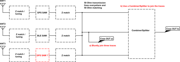
a) Bluntly join antenna traces together into single coax after some impedance transforming and filtering.

b) Use a passive combiner/splitter to join the antenna traces together - in hopes for better isolation when signal is transmitted the other way back.

For the receiving end I would mirror these blocks, before any ANT input on the chips.
schematic

simulate this circuit – Schematic created using CircuitLab

SO basically:

  • 1) Does just joining antenna lines like that make sense or there's smth completely wrong with this idea? (based on the proposed protocols)
  • 2) Would using combiner/splitter make this approach more feasible ?
  • 3) I'm completely off and I should try smth else

In any way I believe I need filtering for each of those bands for sure - in order to get better SNR on my receiving end.

  • GSM filtering is probably more complicated since there's two bands to deal with. That's why it's red on the schematic.
$\endgroup$
6
  • $\begingroup$ you need to do b). Your variant a) doesn't work (unless your "blunt" way of join coaxes amounts to building a wideband impedance matched combiner... in which case a) becomes b) ;) ) $\endgroup$ Commented Jun 25, 2019 at 15:04
  • $\begingroup$ anyway, what is your goal here? What's the purpose of all this? $\endgroup$ Commented Jun 25, 2019 at 15:05
  • $\begingroup$ @MarcusMüller Idea is to join three antennas into one coax. Have that cover some distance and then divide it again on a separate board (idea is not to have three separate wires going full length to my radio receiver board). $\endgroup$
    – crypton
    Commented Jun 26, 2019 at 8:34
  • $\begingroup$ but for what purpose? $\endgroup$ Commented Jun 26, 2019 at 10:30
  • $\begingroup$ erm, umff, that IS the purpose :). I guess to elaborate, maybe 'to achieve easier assembly with a single cable at the expense of more complex hardware... mostly to understand if and how this could be possible to do - so educational purpose as well'. $\endgroup$
    – crypton
    Commented Jun 26, 2019 at 10:37

1 Answer 1

5
$\begingroup$

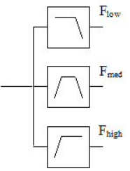
You should use a four-port multiplexer, more commonly known as a triplexer:

enter image description here

As shown in the diagram, a triplexer is a bidirectional device comprising three filters that separate (or combine) the signals from the input (or output) port into band-limited signals at the three output (or input) ports. A properly designed triplexer will present 50$\Omega$ at all four ports across the unit's usable frequency range.

An alternative to the lowpass - bandpass - highpass architecture is to cascade two diplexers, each of which comprises a lowpass and a highpass filter, to produce the desired signal separation.

The specifics of your solution will depend on the required power handling capability and implementation technology (e.g., lumped elements, microstrip, cavity, etc.) An internet search turns up commercial sources for these parts. If you wish to design your own microwave triplexer, you can download Microwave Filters, Impedance-Matching Networks, and Coupling Structures by Matthaei, Young and Jones (part 1 and part 2) from the Microwaves101 web site.

$\endgroup$
3
  • $\begingroup$ Thanks for clarifying. I did look for frequency splitter as well, never came up with this one, cool. I researched further, and so have I understood correctly that I would better use tri/diplexers to separate signals from one coax but to join them I could get away with some single power combiner/splitter, such as for example: SEPS-3-33+ (from mini-circuits) (and then on receiver end use tri/diplexers to separate and pass each frequency to it's radio)? $\endgroup$
    – crypton
    Commented Jun 27, 2019 at 8:48
  • $\begingroup$ A triplexer is a fully bidirectional device, so you should not need to resort to units for separating and combining signal bands. Notice that the total loss from input to any output of the SEPS-3-33+ port is nearly the same; you would have to follow this with filters to achieve triplexer behavior. See, instead, the TPLX and ZTPL parts at MCL, but an internet search for TRIPLEXER reveals TDK and other sources. $\endgroup$
    – Brian K1LI
    Commented Jun 27, 2019 at 13:56
  • $\begingroup$ yes, true. Thank you for your input. I think I have what is needed. Need to prototype it :P. Cool! $\endgroup$
    – crypton
    Commented Jun 27, 2019 at 15:12

You must log in to answer this question.

Not the answer you're looking for? Browse other questions tagged .