3
$\begingroup$

There are a ton of old USSR Gunn diodes available on ebay and I'm looking for a cavity that can make use of them. I am willing to machine one myself if necessary, but I'm unable to find any decent schematics. They either leave info out or they look way too complicated and include something that doesn't even look like the correct design.

If it is possible to buy one to fit these, that'd be perfect, but I can't find it.

I see some gunnplexers on ebay, but I don't know if they will fit the diodes that I want to use. Are there any other variables aside from frequency and the actual mounting hole diameter for the diode itself? So maybe I could just hack it in place.
$\endgroup$
6
  • $\begingroup$ hey, cool project! Can you tell us for what specifically (and which frequencies) you're planning to use that? $\endgroup$ Commented Jun 10, 2019 at 9:40
  • $\begingroup$ I plan on doing a youtube video on making a simple cheap microwave link for various purposes. $\endgroup$
    – Synaps3
    Commented Jun 10, 2019 at 21:33
  • 1
    $\begingroup$ I forgot to put X-band in there. I plan to use ~10GHz and a satellite LNB to receive into a generic FM receiver in the 800-900 MHz range. I will modulate the gunn diode by capacitance coupling audio to supply voltage. Don't know it will work, but I think so. $\endgroup$
    – Synaps3
    Commented Jun 10, 2019 at 21:35
  • $\begingroup$ I really just need the most basic measurements for a cavity. The one below seems beyond my needs. None of the other schematics I see have a "choke block" $\endgroup$
    – Synaps3
    Commented Jun 10, 2019 at 21:39
  • $\begingroup$ As said, that is a very cool project, and pretty involved! $\endgroup$ Commented Jun 11, 2019 at 11:55

1 Answer 1

3
$\begingroup$

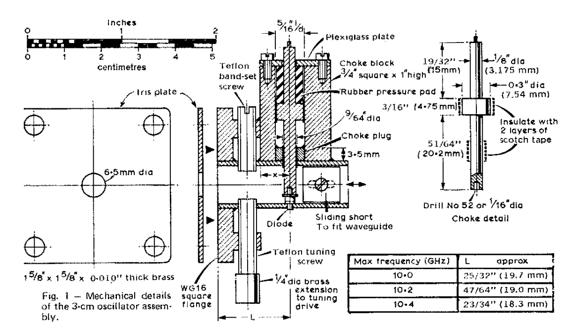
You might be able to use this mechanical drawing, from the ARRL's monthly QST magazine for August 1974, to determine whether the available units are appropriate to your needs:

enter image description here

$\endgroup$
4
  • $\begingroup$ Thanks. I don't understand the purpose of that top cavity however. It looks to be called the choke block. $\endgroup$
    – Synaps3
    Commented Jun 10, 2019 at 21:29
  • $\begingroup$ I thought the RF radiates from the iris, but they show it going through that choke block thing. $\endgroup$
    – Synaps3
    Commented Jun 10, 2019 at 21:30
  • 1
    $\begingroup$ @Synaps3 It looks to me like RF exits through the 6.5mm diameter circular opening at the center of the iris plate. The iris plate mounts on the WG16 square flange. WG16 is spec'd for 6.557 to 13.114GHz operation. $\endgroup$
    – Brian K1LI
    Commented Jun 10, 2019 at 23:58
  • $\begingroup$ @Synaps3 the choke block with that spindle-thingie which acts as current feed to the diode is actually a cavity of its own, instead of being a electronic component. Just "replaces" a coil (which could never have the Q of a cavity). $\endgroup$ Commented Jun 11, 2019 at 11:54

You must log in to answer this question.

Not the answer you're looking for? Browse other questions tagged .