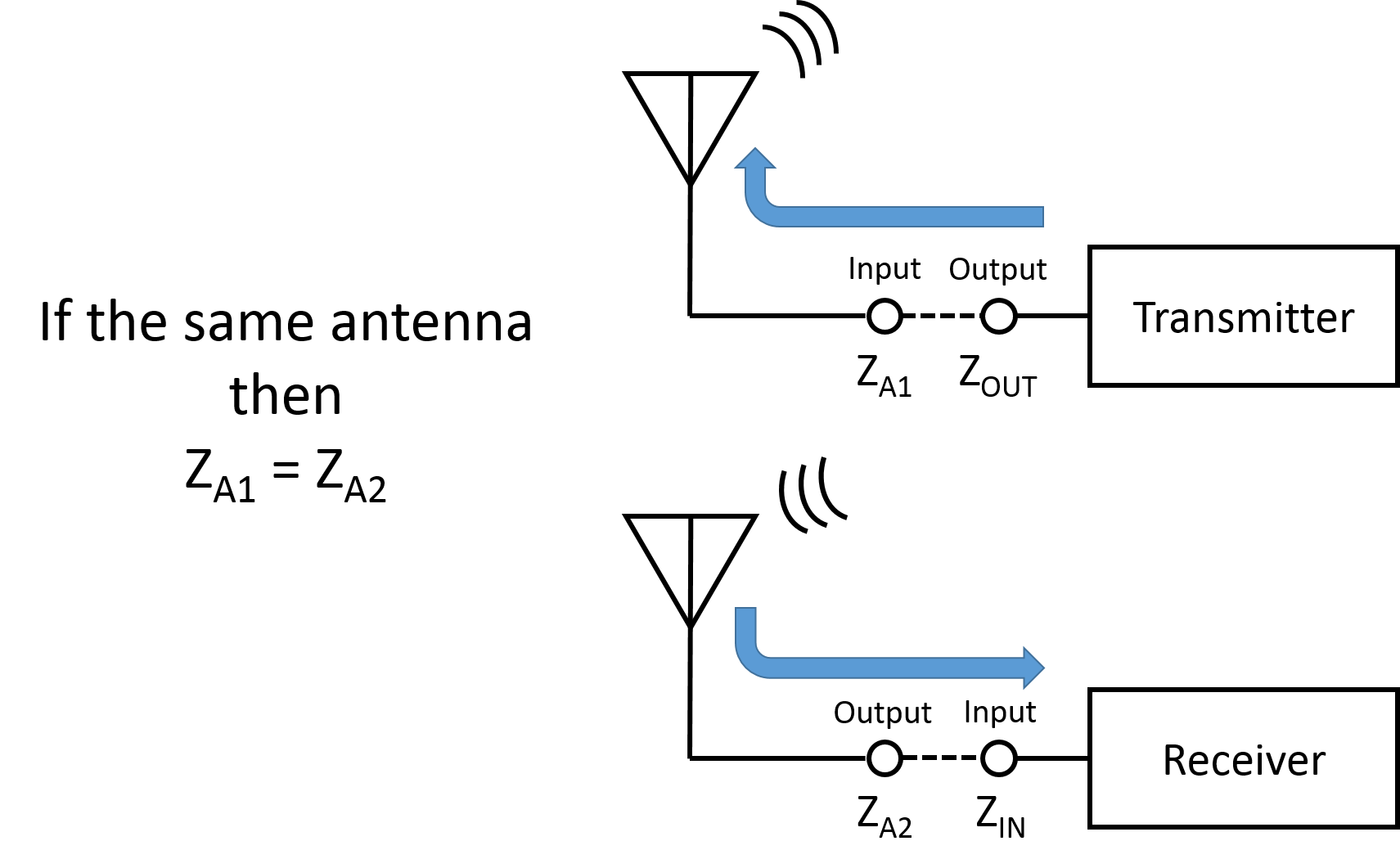
It is common convention to represent input and output as dictated by the signal flow (or more strictly current flow). A transmitter emits a signal from its output. Its output has an associated impedance. A receiver processes a signal from its antenna connection. This is therefore an input with an associated impedance. A circuit that connects to an output generally does so through its input and visa versa.
An antenna is capable of receiving RF signals and transmitting RF signals. In the case where it is receiving signals, the antenna is considered the signal source (an output) to the remainder of the circuit such as a receiver or measurement instrument which is the load (an input). In the case where the antenna is transmitting signals, it is regarded as the load (an input) for the transmitter or measurement instrument (an output).
The antenna has a measurable impedance at its feedpoint. The impedance is the same for transmitting (input impedance) and receiving (output impedance). It is generally easier to measure the input impedance of the feed point while injecting a signal into the antenna's feedpoint and measuring (or calculating from other measurement points) the resulting complex current and voltage at the antenna feedpoint. This is what is happening when you measure the impedance of the antenna with a one port VNA configuration. While this technique measures the feedpoint (input) impedance of the antenna while transmitting, the feedpoint (output) impedance during receive can be inferred due to reciprocity.

It is generally desirable that we match the impedance of the load connected to a signal source to the impedance of the signal source in order to achieve the rated or desired power transfer. In RF work, the impedance that is commonly used by convention is 50 ohms but this is by no means a requirement.
In the case of a transmitter which has a 50 ohm load specified, the rated power of the transmitter will be realized when the load is also 50 ohms. This wording is specifically chosen - you should not infer "maximum power is transferred" since often the output power of a transmitter is rated for a specific load impedance but the output impedance of the transmitter may be something other than 50 ohms (for example, to improve the efficiency of the transmitter).
When an antenna is the load for the transmitter, it is then desirable to have an antenna with a 50 ohm impedance. Fortuitously, if the transmitter is part of a transceiver, the transceiver's receive antenna impedance is also typically specified as 50 ohms. Once again, do not infer that "the input impedance of the receiver is 50 ohms" but only that it is specified to connect to a 50 ohm antenna.
This notion of the specified impedance verses the "actual" input or output impedance becomes burdensome to articulate, so often the shortened term "impedance" is used in favor of the more accurate, albeit verbose, form of "the specified antenna impedance".
When an antenna feedpoint impedance is not the desired impedance, such as 50 ohms, then a matching network can be used to transform the feedpoint impedance of the antenna to the desired impedance. The matching network is a two port device. One port is connected to the antenna. This port is designed to be a conjugate match to the impedance of the antenna. The other port of the matching network connects to the transmitter/receiver. This port is typically designed to be 50 ohms or whatever is called for in the transmitter/receiver specification. In combination, these two ports transform or match the impedance of the antenna to the impedance of the transmitter/receiver specification.
Since the antenna feedpoint impedance is the same under transmit and receive conditions, the two port matching network performs the matching function in both use cases. But these matching networks are not lossless. The losses can be asymmetric. The capacitors, inductors, and transformers used in such networks waste power in the form of heat. The design topology and components are generally optimized to minimze these losses.
Typically a fixed value antenna matching network is designed by measuring or calculating the feedpoint impedance of the antenna (without any matching network) and calculating the requisite values. This calculation used to be a laborious hand calculation but there are now many on-line tools that remove the burden. For example, for designing L type matching networks, I prefer the http://leleivre.com/rf_lcmatch.html site.
Once the values of the matching network have been calculated and a prototype built, it would be possible to place this circuit on a VNA and measure the transformation characteristics using a two port technique. But it is often easier to attach the matching circuit to the antenna and measure the input impedance of the remaining open port using a one port measurement and make appropriate adjustments from that point. The one port VNA measurement technique is such an example. Since the goal is to have the input of the network match the specified transmit/receive impedance, a one port measurement directly provides the necessary information.
