3
$\begingroup$

If I connect two antennas to one radio using a t connector will it work?

If a connect 2 antennas (a mag mount + a dipole?) to the same radio with an adapter will it work normally on 2M band and will it cause extra interference?

Also, if it works would this give me an added range/better signal over using just one of the antennas?

$\endgroup$
7
  • 1
    $\begingroup$ I wouldn't try transmitting: the SWR is unknown (likely high). $\endgroup$
    – glen_geek
    Commented Mar 4, 2018 at 18:34
  • $\begingroup$ @glen_geek why should it? I'd assume that you'd build an impedance matching divider. $\endgroup$ Commented Mar 5, 2018 at 16:50
  • 2
    $\begingroup$ @MarcusMüller A "T" is a crude parallel connection, as GlennW9IQ has pointed out. Furthermore, those two antennas may couple with unknown phase, yielding even more SWR uncertainty. And who knows what radiation pattern results? $\endgroup$
    – glen_geek
    Commented Mar 5, 2018 at 17:15
  • $\begingroup$ @glen_geek not seen many of these Tees in my time - but I've been either playing with RF measurement-device Tees (which are matched 50Ω on all ports over a significant frequency range for obvious reasons), or with BNC tees designed for network building (which are typically 75Ω with some impedance matching for a rather narrow band). $\endgroup$ Commented Mar 5, 2018 at 17:21
  • $\begingroup$ @MarcusMüller Really? You don't have 10 of these in your adapters drawer? amazon.com/C2G-Cables-Go-02047-T-Adapter/dp/B0000510YX/… $\endgroup$ Commented Mar 5, 2018 at 17:52

5 Answers 5

8
$\begingroup$

If I connect two antennas to one radio using a t connector will it work?

That depends on your t-connector.

If your tee really is just a branch in the inner conductor and connected outer conducters, than the other two answers are correct: your input impedance will be different than your output impedance.

If, however, the tee is meant to be used in a system with constant impedance, and most are, then it's going to be built in a way that matches all inputs.

In your specific case, there's good reason to simply implement such a splitter yourself, as you want to have control over the splitting/combination.

The typical way to do that here is the Wilkinson Power Divider in coaxial implementation:
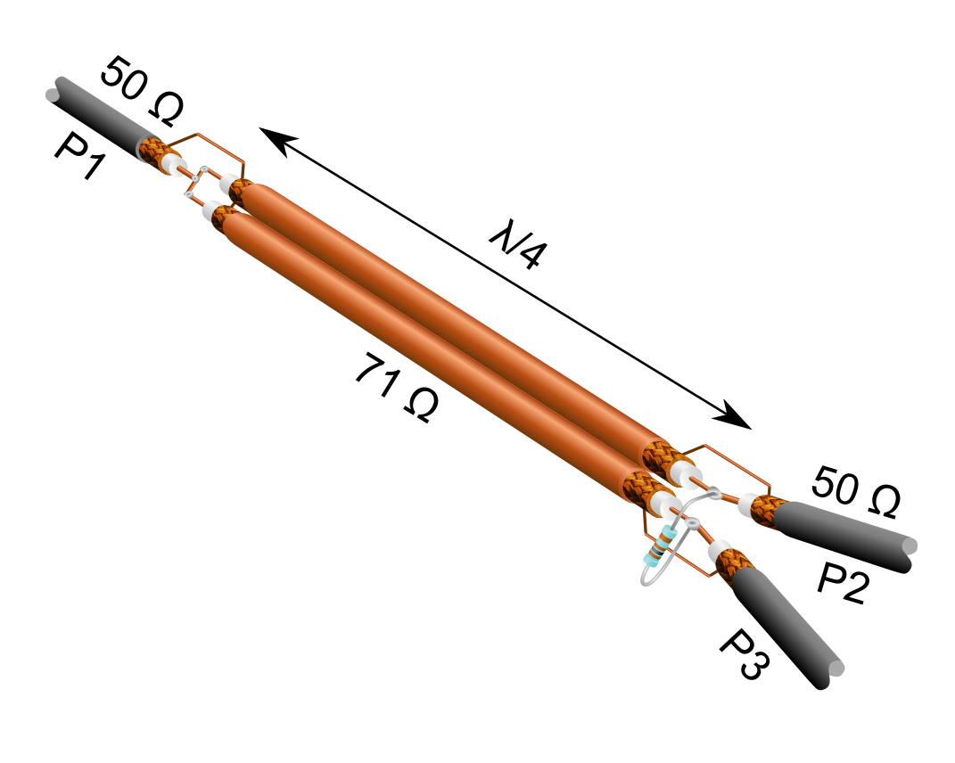
Wilkinson Divider in coax impl

With that, not only do you split the power half and half (if you transmit into P1), or combine with equal gain (if you receive on P2 and P3), but you also isolate P2 and P3, meaning that no power from P2 ends up on P3 and vice versa.

I was just assuming you're using 50Ω line; if you're not, that $\frac\lambda4$ piece needs to be $\sqrt2$ of your system's impedance.

71Ω might be hard to get, 75 Ω usually easy; the mismatch should be minimal.

If a connect 2 antennas (a mag mount + a dipole?) to the same radio with an adapter will it work normally on 2M band

What's "normally"?

I guess no, this is not going to work like you expect: you combine/split equally. That means you've just built an antenna array out of two completely different antennas. That array will have a directive gain depending on the phase, efficiency and relative position of the two antennas that will be practically impossible to predict without extensive simulation.

and will it cause extra interference?

Interference will be picked up as before, but you have a directional antenna now. So, you might be getting more or less interference, depending on where your sources of interference are relative to the antenna system pattern described above.

Also, if it works would this give me an added range

Only if the above directional gain points in the direction you want to work

/better signal

same

over using just one of the antennas?

What you want to have seems to be diversity gain. ON5MF's answer actually already describes one diversity reception method:

Selection combining, where you simply switch to the one antenna that has better SNR.

Assuming you place the two antennas far enough so that their reception paths are uncorrelated, you'd get a diversity gain of 50% (assuming independent, Rayleigh-distributed paths). That means, having the second antenna to select from gives you, on average, an SNR that you work with that's 50% better than if you had nothing to choose from.

If you'd want to have real combining gain, you'd need two independent receivers. Ideally, you'd do optimum combining (since you mention the presence of interference), but to limit complexity here, you'd normally just start with two synchronous receivers, and add up their signals, weighted with a factor that has an amplitude that reflects the SNR of that single receiver, and a phase correcting the receive phase. That would give you an SNR that is the sum of the two received SNRs.

This second solution, however, would require a dual-channel synchronous SDR solution, and I'd guess you don't have that lying around, so:

As ON5MF suggested, get a switch. A good idea would be to monitor the "unused" channel with a cheap RTL-SDR to notice if the signal strength or interference level suddenly changes and switching might make sense again.

$\endgroup$
8
$\begingroup$

Assuming that both antennas are 50 Ω resistive, they will combine in parallel for a 25 Ω load impedance when transmitting. This will cause the transmitter to see a 2:1 SWR. This is a 0.333 voltage reflection coefficient so ~11% of the transmitter power will be returned to the transmitter from the tee junction. The remaining 89% of the power will be split between the two antennas resulting in approximately 44% of power to each antenna. The net effect is an ~ 3.5 dB loss to each antenna.

The above scenario assumes that the transmitter does not further fold back the output power as part of an SWR protection mechanism nor does the transmitter final burn out due to elevated SWR.

If you wish to deploy an antenna with additional gain, you will be far more successful with a purpose built antenna for that purpose.

$\endgroup$
4
  • $\begingroup$ That's not inherently true. A t-Connector can just as well be impedance matching (see: Wilkinson Divider). $\endgroup$ Commented Mar 5, 2018 at 16:48
  • 1
    $\begingroup$ @MarcusMüller To make a Wilkinson divider, you would need an additional 2Zo resistor in the mix. I didn't see that in the OP's description. $\endgroup$
    – Glenn W9IQ
    Commented Mar 5, 2018 at 17:25
  • $\begingroup$ Ah, true! But when I read "t connector", I simply assumed it's a properly matched power divider. $\endgroup$ Commented Mar 5, 2018 at 17:36
  • $\begingroup$ ... I'd agree, that was probably unwarranted, so I inverted my downvote to an upvote. $\endgroup$ Commented Mar 5, 2018 at 17:37
6
$\begingroup$

For receiving it should work up to a certain level.

However, the impedance will be completely different from that of a single antenna. So the SWR will be too high for transmitting and reception will normally be less efficient than with a single antenna.

The best way to use two different antennas is to use a coax switch.

$\endgroup$
0
1
$\begingroup$

Use a Duplexer and it will manage your issues that are described. Not as cheap but a far better and safer solution. Assuming that both antenna's are for separate bands. If your trying to use both antenna on a single band, then a switch. Leave the Tee fittings to the CB group. Also, talk around your local radio club, the elmers are always willing to help!

$\endgroup$
0
$\begingroup$

We are tracking wild animals with VHF receivers where incoming signal sounds like high pitch impulse in every 2 seconds. Distance and environment factors are impeding signal strength so I recently added one extra whip antenna to existing one on car roof (distance 0,9 m) with BNC plug-2xBNC socketBNC plug-2xBNC socket.

I can say that the incoming signal improved significally as I was hearing clear signal with two antennas from distance of 700 m and no signal with one antenna and same receiver parameters.

$\endgroup$

You must log in to answer this question.

Not the answer you're looking for? Browse other questions tagged .