3
$\begingroup$

I'm trying to understand a component of an AM radio kit that I have. (There is a document available here: https://www.elenco.com/wp-content/uploads/2017/10/AM-780K_REV-K-2.pdf describing the build procedure and the circuit in more detail.) I was researching coil windings for a regenerative receiver, that had me come back to this circuit, and there are some things I don't understand. The radio works great, I just have some questions about it.

The part I'm confused about is the bottom left of the circuit diagram (L1, L2, and C2):

AM780K circuit diagram

Is there any reason why L1 and L2 are in series like this? Is there any difference between a component with C2 and L3 = L1 + L2 and a component with C2, L1 and L2?

Also, I'm a little confused by the diagram showing 1,2,3, and 4 as antennas. Can I add an external wire to act as antenna somewhere in this component?

Other diagrams show taps in the coil to switch between different resonant frequencies (adjusting the length of the coil) along with the variable capacitor. I was wondering if these points are potentially taps, as well.

$\endgroup$

3 Answers 3

4
$\begingroup$

Is there any reason why L1 and L2 are in series like this? Is there any difference between a component with C2 and L3 = L1 + L2 and a component with C2, L1 and L2?

There is essentially no difference than a single coil (other than the impedance effects of the extra bit of wire leaving the coil and coming back, which will not be much at all). They probably used whatever pre-wound coil was available cheaply, or was used in another kit they sold, and decided that the inductance of the two coils in series best suited this circuit.

Also, I'm a little confused by the diagram showing 1,2,3, and 4 as antennas.

That is not an antenna symbol, but a symbol for a contact or test point. The antenna symbol you are thinking of looks like this, with three spreading lines in a triangle:

Antenna symbol

The antenna symbol can also lack the horizontal bar of this example.

Notice that the same symbol appears on the connections of the speaker. They seem to have used this symbol simply to label the points in the diagram where, when you assemble the circuit, you solder a wire from a component (the coil and the speaker) to a labeled point on the circuit board. I would not call this good practice in a schematic, because the signal does not actually pass through those connection symbols. It would be more conventional to simply place a label next to the wire itself.

The antenna in this circuit is the coils — a ferrite rod antenna. Perhaps you could in fact usefully improve its reception by attaching an external antenna somewhere, but I don't think this circuit was particularly designed for that.

$\endgroup$
3
  • 1
    $\begingroup$ I think L1 and L2 comprise the antenna. They will be wound on a ferrite rod. $\endgroup$
    – tomnexus
    Commented Dec 12, 2022 at 4:22
  • $\begingroup$ Maybe those test points are for jumper wires, to change the inductance and thus the frequency? $\endgroup$ Commented Dec 12, 2022 at 15:31
  • 1
    $\begingroup$ @MikeWaters I'm quite confident that they are just named solder points, because the set of circuit nodes with the symbol is exactly the same as the set of circuit nodes that are marked on the PCB itself, and there's little reason to mark "-SP" as that rather than just "GND" if it were a test point. $\endgroup$
    – Kevin Reid AG6YO
    Commented Dec 12, 2022 at 16:21
1
$\begingroup$

Is there any reason why L1 and L2 are in series like this? Is there any difference between a component with C2 and L3 = L1 + L2 and a component with C2, L1 and L2?

It's just because of the parts in their kit. They sell you a loopstick antenna, which has a tap somewhere in the middle (not actually right in the center), so that you can get three different values of impedance by choosing which two points to connect. In this circuit, they're using the whole thing, and the middle tap isn't connected to anything (except the "2" and "3" points on the board, but they aren't connected to anything except each other). They have other designs which presumably use different connection arrangements, but they all use the same "1, 2, 3, 4" connections to the board.

Also, I'm a little confused by the diagram showing 1,2,3, and 4 as antennas. Can I add an external wire to act as antenna somewhere in this component?

As Kevin says, those symbols aren't antennas, they're markers for points on the Elenco PCB, and they don't really mean anything schematic-wise.

But the actual antenna in this schematic is L1+L2 — it's meant to represent a loopstick antenna, not plain old inductors.

All that said, if you wanted to use a long wire I think you could replace L1+L2 with a ~600uH inductor, and attach the wire to the non-grounded (right) side of it, but I'm a software nerd :)

$\endgroup$
1
$\begingroup$

That ferrite-rod coil likely is a component adapted by ELENCO for this circuit, but was originally intended for superhet-style transistor AM radios.
I can't imagine that ELENCO would really want the two-coil complication where bad-soldering can cause so many problems, and where colour-coded wires can be soldered to wrong PCB pads...a simple coil winding with two wire ends would be far less troublesome.

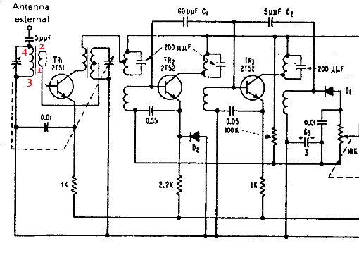
Here is how such a ferrite-rod antenna might have been originally used in a transistor radio. Red numbers refer to OP's coil connections. This particular transistor front-end is an autodyne mixer/oscillator. TR1's base is driven from the coil's low-impedance winding (untuned). Variable capacitor tunes coil 3-4 to the AM radio station frequency:
Sony TR-55 circuit diagram


This schematic fragment of a Sony TR-55 5-transistor radio shows how an external antenna might be added, perhaps a short "whip". (5 uuf = 5pf)

$\endgroup$
1
  • $\begingroup$ Thank you for this info, I think you're right. Why this part was included was really interesting to me. @hobbs also mentioned here that "they have other designs which presumably use different connection arrangements", too. Your answer mentions the superheterodyne AM receiver, and up until now I was just working on the regenerative and the circuit I linked above. I also have Elenco's AM/FM-108CK (I haven't put together yet) which has the same series inductor as the kit in the 708K, but for the superhet receiver in the 108CK. It's useful in that kit! $\endgroup$
    – Jared
    Commented Dec 18, 2022 at 22:39

You must log in to answer this question.

Not the answer you're looking for? Browse other questions tagged .