4
$\begingroup$

I've been working with Xnec2c to model a 40 meter vertical antenna I want to build for field QRP. This antenna is short at 25 feet and uses a 1:1 unun at the base with 4 radials.

The model has the load placed 1/4 of the way up (~6 feet). The model load is 35uH and 17pF. I've used toriods.info to pick an FT37-43 to have 10 turns. The web app reports that the inductor will have 12 pF. So I'm adding a trimmer cap in series.

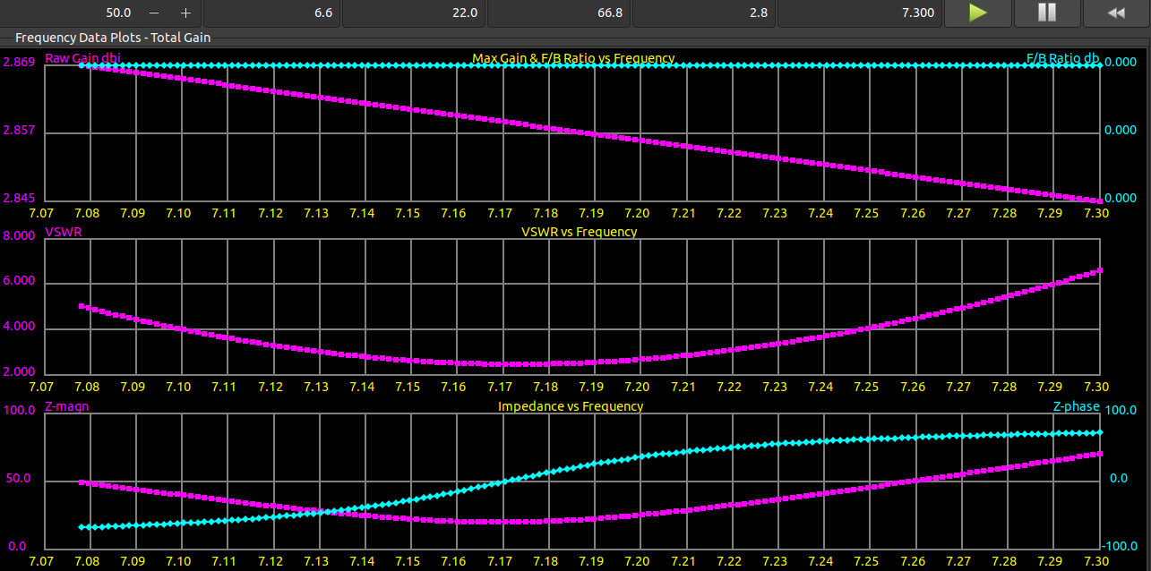
My understanding is that b/c the antenna length is not close to being resonant, the Q must be quite narrow. I recall from my basic LRC theory, that R can widen the Q. So I added 20 Ohm to the model and sure enough the SWR flattens somewhat.

It seems like a really bad idea to add a resistor to an antenna in this way. The gain without the resistor is ~2.9 dBi. That's almost half power.

Is using a resistor like this done ?

First plot is with resistor and the second without.

UPDATE MODEL

I created 4 wire radials with excitation cards for each with -0.25 V with the vertical segment having 1 V. Then used the Sommerfeld-Nortonoption in the GN card. The losses were substantial for varying parameters. The antenna went far out of tune.

This really brought home to me the concept of the radials and RF ground.

BUILD

I finished building the antenna with the same design spec with the exception of a wider range trimmer capacitor. I tuned the trimmer cap in my basement under very non-ideal conditions, to the lowest SWR of 18.

I then hung the antenna down my back stairs and connects three radials. The SWR was ~13 so I swapped the 1:1 unun for a 9:1 and the SWR lowered to ~1.3 without a tuner. This is all done at 7.125 +- 0.300 MHz.

I made a contact to someone doing POTA. Very satisfying.
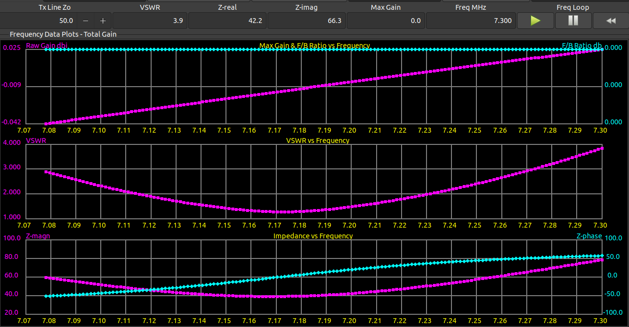
With 20 Ohm Resistor No Resistor

$\endgroup$

2 Answers 2

2
$\begingroup$

Great work so far!

It's reasonable to add a resistor to increase the bandwidth - if you're not using a tuner, so you need it to work in various situations and across the band, then it's your only real option. It will be less efficient but that's the trade-off. Many HF antennas are worse.

uild and measure it in situ before adding resistance. I think you'll find the input R is a lot more than you expect, because of ground losses, and these will also reduce the Q and increase the bandwidth. The same loss of course, just the power is being dissipated in the ground instead of in the resistor.

Most kinds of NEC can simulate a Somerfeld-Norton ground. Try simulating with a lossy ground and see what happens to the impedance. Keep the wires several radii above the ground for most accurate results. Use this table of earth parameters to select something reasonable for your situation:

Description Conductivity (S/m) Relative permittivity
Fresh water 0.001 80
Salt water 5 81
Pastoral, low hills, rich soil. 0.0303-0.01 14-20
Flat country, marshy, densely wooded 0.0075 12
Pastoral, medium hills and forestation 0.006 13
Pastoral, medium hills and forestation, heavy clay soils 0.005 13
Rock soil, steep hills, typically mountainous 0.002 12-14
Sandy, dry, flat, coastal cities, industrial areas 0.001 5
Cities, heavy industrial areas, high buildings 0.001 3

These are from the SuperNEC GUI URM, sadly very hard to find online. The manual is part of the supernec package which you can download.

Finally - In the 40 m band, 24 feet is almost a quarter wave tall, so you should get enough bandwidth for your part of the band. Couldn't you add some top loading (a T or even just a single wire hanging to one side) to make it resonate, instead of using an inductor?

$\endgroup$
5
  • $\begingroup$ Love that chart. I'm checking on the other points you made. I think the SN method will not work with Xnec2c when using the radial options, will double check. $\endgroup$
    – wbg
    Commented Jun 24, 2022 at 3:46
  • $\begingroup$ Yes this list is Gold. I think the real ground is all specified in one GN card. But you need to draw the radials as wires 10*r above ground, not use a radial ground screen card, if there's such a thing. $\endgroup$
    – tomnexus
    Commented Jun 24, 2022 at 3:53
  • $\begingroup$ My first attempt was to draw in the radials and set the excitation to -1 V. It didn't turn out so well so I went with the GN card's option of radial ground screen. $\endgroup$
    – wbg
    Commented Jun 24, 2022 at 4:20
  • 1
    $\begingroup$ I looked it up, yes GN can do the wires, but I don't know if it does wires and realground together. Drawing them by hand isn't a problem, just be sure they all meet at 0,0,z where z is somehat above zero. Keep the segments a full $\lambda/10$ so they're nice and long, short segments meeting at 90 degrees or less is asking for trouble. $\endgroup$
    – tomnexus
    Commented Jun 24, 2022 at 4:25
  • $\begingroup$ I drew them in b/c you cannot use the lossy ground and radials on the same card. I also have a near field (NE) card in there I learned from an example. In past experiments things didn't work w/o it. But maybe now I can toss it. My rad pat with drawn radials and lossy GN is a sphere. $\endgroup$
    – wbg
    Commented Jun 24, 2022 at 4:44
2
$\begingroup$

Is using a resistor like this done ?

Occasionally (the best known example is probably the terminated folded dipole, which places the resistor at a point that has zero current at frequencies where the antenna is resonant), but there are a few things to consider:

  1. Efficiency. I'm sure you realize this already, but lowering the Q like that will definitely knock a few dB off of your transmitted signal — about 2.8dB judging by the graphs you posted.

  2. Power handling. I know you said QRP, but how QRP is QRP? You'll be putting almost half of your output power into the resistor, which then has to get rid of it as heat. So make sure you use a resistor with a high enough power rating (or several higher-value resistors in parallel).

  3. Inductance. Wirewound resistors and many kinds of film resistors have more inductance than a bit of wire of the same length, because they're basically coils. When you add an R to your model, it will assume it's a pure resistance. Either make sure to get a low-inductance type, or be prepared to tweak your loading coil specs to compensate.

All that said, I tend to agree with tomnexus that, in the case of a vertical, you probably already have a 10 or 20 ohm resistance in the form of ground loss, so if your model isn't already taking that into account, it's lying to you, and you need to either add ground loss to your model before you go further, or just build and test (without the resistor).

$\endgroup$
3
  • $\begingroup$ Great point about resistors being inductive. I know that the wound wire type are but didn't think the carbon ones would be. But again the carbon are not made in the 5 watt range I think. QRP for this is 4-6 Watts. $\endgroup$
    – wbg
    Commented Jun 24, 2022 at 3:47
  • 2
    $\begingroup$ @wbg there are several different kinds of "carbon" resistors, and some of them use a carbon film that's cut into a helix quite similar to a wirewound. It's not always easy to tell what you're getting. There are also wirewound ones that use a pair of opposite helices, or a "there and back again" bifilar arrangement, to achieve very low inductance, but they tend to come with special prices. $\endgroup$ Commented Jun 24, 2022 at 4:18
  • 1
    $\begingroup$ There are non-inductive (and non-carbon) resistors available, do a search for 'non-inductive power resistor'. Example: Caddock MP930-20.0-1%, thick film TO-220. $\endgroup$
    – VE3LNY
    Commented Jun 26, 2022 at 12:50

You must log in to answer this question.

Not the answer you're looking for? Browse other questions tagged .