I have designed a half-wave dipole antenna for frequency range of 150 to 200 MHz. Due to resonant frequency of 175 MHz, Its dimensions are: L=817.44 mm, R=1.71 mm. Impedance is also equal to 73 ohms. After simulating in CST MWS, the bandwidth was about 18.64 MHz. How I can increase the bandwidth? I want to use this antenna for frequencies of 150 to 200 MHz. What's the method?
-
1$\begingroup$ Hello Mohammadsadeq, and welcome to ham.stackexchange.com! $\endgroup$– rclocher3Commented Aug 13, 2020 at 13:29
-
4$\begingroup$ With a folded dipole I've managed 136-174 MHz, under 1.5:1. But you should explain what is the real problem you're trying to solve? Is this homework (so use a fat bicone, a thick cylinder, a matching network?) or a product design? $\endgroup$– tomnexusCommented Aug 13, 2020 at 13:45
4 Answers
Marcus and Richard have answered the question that you asked, how to triple the bandwidth of a dipole, with the correct answer that it can't be done. I suggest that you edit your question to give us more information about the problem that you're trying to solve and its constraints, and then we can offer more targeted suggestions. In the meantime, here are some generic suggestions of ways to increase bandwidth of an antenna system:
Use a log-periodic antenna. There are many existing commercial antenna models that use a log-periodic for the 174–216 MHz VHF television band.
Use a discone antenna.
Redesign the radio to tolerate a larger impedance mismatch. This would not be easy for a high-powered transmitter.
Use an automatic antenna tuner.
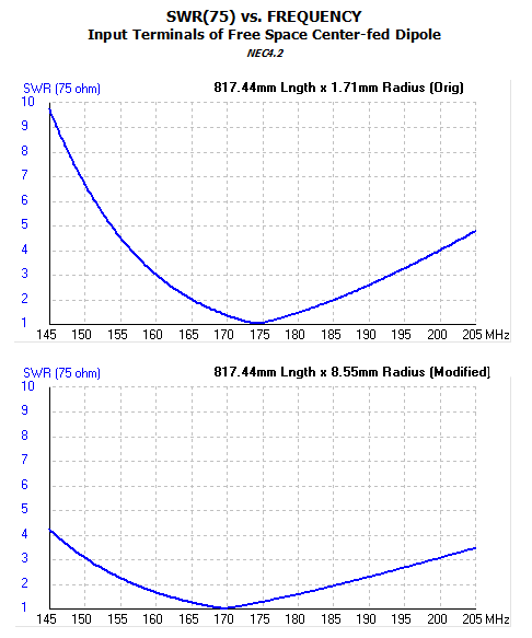
You might experiment with increasing the diameter of the conductors of the dipole to improve its SWR bandwidth, along with optimizing the physical lengths of those conductors (equally) to center the low-SWR bandwidth of the dipole in your r-f spectrum of interest.
Author edit of 14 Aug 2020:
Below for "calibration" is a comparison of a case where the radius of the conductors stated in the OP was increased by a factor of 5:
-
$\begingroup$ Yep, diameter variation is a usual technique, but I doubt he can triple the bandwidth that way. $\endgroup$ Commented Aug 13, 2020 at 10:39
-
1$\begingroup$ discone? i.e., variable diameter... $\endgroup$ Commented Aug 13, 2020 at 12:13
-
$\begingroup$ Thank you so much. The bandwidth increased to about 27 MHz by 8.55mm radius. $\endgroup$ Commented Aug 17, 2020 at 7:38
After simulating in CST MWS, the bandwidth was about 18.64 MHz.
According to which definition of bandwidth?
I'm asking this because every antenna is a tradeoff. The easiest way, probably, to deal with this is to simply reduce your requirements for what "bandwidth" is.
How I can increase the bandwidth?
You're using a dipole, but you want a bandwidth of more than a fourth of the center frequency.
That's usually not going to work; you need a different design if you need to use a bandwidth that large relative to your center frequency, or relax your definition of "bandwidth".
You can of course help the situation by doing as Richard recommends: a larger-diameter conductor usually helps a bit with bandwidth, but I don't think you'll increase your bandwidth by a factor of 3 that way.
-
$\begingroup$ 18.64 MHz is according to Return loss plot, using -10 dB levels. Our goal is to obtain desired bandwidth in the base of a dipole antenna; May I use LPDA structure or there is a better method? $\endgroup$ Commented Aug 17, 2020 at 7:21
-
$\begingroup$ either you build a dipole, or a LPDA, those are two different antennas $\endgroup$ Commented Aug 17, 2020 at 9:08
You can increase the bandwidth of a dipole by adding capacitive hats (you may have to shorten the dipole to maintain a given resonant frequency). Conical hats, hemispherical hats, or hats with a circular rim will work better than short 90 degree radial spikes at the ends, or an H shaped dipole.
Small capacitive hats might even raise the radiation resistance, as well as broadening the dipole's bandwidth. Maybe 10% or less in size compared to the long dimension of the dipole (which, again, will have to be resized to re-center the resonance frequency to the desired value.)
You also can increase the bandwidth by adding wires spread apart a little, and turning your dipole into either a cage dipole or a fan dipole. A fan dipole with each fan element a slightly different length will also broaden the bandwidth.
At the limit you can turn these (fan or cage) wires into conical sheets centered at the feed, and end up with a discone or biconical dipole, which have much wider bandwidths than a wire dipole (but are still 2-element dipoles of a sort).
-
$\begingroup$ Thank you kindly. Does capacitive hat increase the bandwidth by a factor of 3? and Can I implement capacitive hat in CST MWS? $\endgroup$ Commented Aug 17, 2020 at 7:27
