5
$\begingroup$

I am looking at using NEC to model a $0.5\lambda$ rectangular folded dipole, for closely spaced larger sides (choosing a separation of $0.01\lambda$).

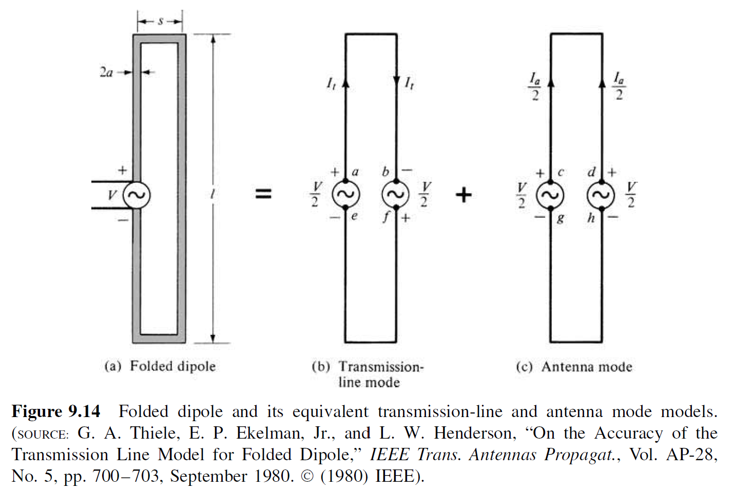
In Antenna Theory, Analysis and Design by Balanis, the folded dipole is touched upon, and an equivalent antenna mode circuit is presented:

balanis-figure-9.14

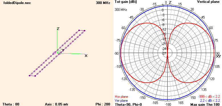
I created a NEC model for this to show the geometry and pattern. Auto-segmentation is used with 20 segments/$0.5\lambda$. The larger sides of the model point in the same direction, so the voltage source matches the antenna mode circuit. The magnitude of the impedance is $213\Omega$.

folded-dipole-model

Some questions I have:

  • How can I verify this model? The pattern and peak gain is very similar to the standard dipole. Are there any limitations due to NEC?
  • Is the purpose of using 1 voltage source on each of the larger sides is to ensure to current is identical in each?
  • The gain of a standard 0.5$\lambda$ dipole can be theoretically derived as $2.15$ $dBi$. Does a similar derivation exist for a folded dipole, taking into account the separation length?

Edit: As suggested, I have made the following updates:

  • Updated segmentation to 10 segments/0.5$\lambda$.
  • Wire radius at $0.001\lambda$, which satisfies $r < L/10$ before/now.
  • Using only a single source, in the $+\hat{x}$ direction.
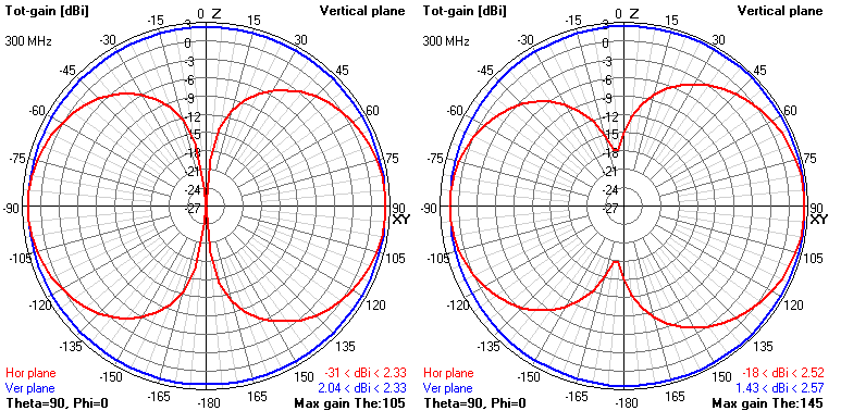
  • Simulate for separation of $0.01\lambda$ (left) and $0.1\lambda$ (right).

folded-dipole-model-seperation

The single source makes the elevation pattern non-constant, peaking at $\pm 15\deg$ and $\pm 55\deg$ respectively to broadside. The magnitude of the impedance is $417\Omega$ and $647\Omega$ respective.

The standard dipole impedance was $95\Omega$. In Balanis it was stated the impedance of a short-separation folded dipole is 4 times the impedance of the standard dipole, which is approximately true in this model.

Some follow up questions:

  • How can I know if the pattern and gain of my folded dipole is correct? I was under the impression a folded dipole pattern/gain is very similar to the standard dipole.
  • If I feed from the $-\hat{x}$ direction as shown in Balanis, my front lobe is smaller than my back lobe. Why is this the case?
$\endgroup$
6
  • 1
    $\begingroup$ 1. Your model looks OK - quite a lot of segments, you should probably drop to 20/lambda. Make sure you respect the 2:1 thickness rule, better stick to 5:1 (so with short segments like this, the wire radius must be quite small). $\endgroup$
    – tomnexus
    Commented Dec 11, 2019 at 7:29
  • 1
    $\begingroup$ 2. But in NEC you don't really need two sources, unless you want to fully investigate the two superimposed modes of the folded dipole. A folded dipole is fed from one side. Effectively the two superimposed sources on the other side add up to zero - see how they have opposite polarity. So remove one source and see how it looks - edit your question to include impedance too. $\endgroup$
    – tomnexus
    Commented Dec 11, 2019 at 7:32
  • 1
    $\begingroup$ 3. When you've removed one source, you should start to see a slight variation in the "azimuth" pattern - it won't be completely flat. More separation makes it more variable. Perhaps increase the separation to lambda/10 to make it more obvious. You might need to adjust the graph scale to see it. $\endgroup$
    – tomnexus
    Commented Dec 11, 2019 at 7:36
  • $\begingroup$ @tomnexus Thank you for the feedback, I have updated the question with your comments. $\endgroup$ Commented Dec 11, 2019 at 10:05
  • $\begingroup$ A really nice way to feed a VHF folded dipole is to run coax through a hole in the center of the shorted leg around one loop and then when it comes out at the feedgap connect the outer to the leg it's coming out of and the inner to the other side. . You need no balun $\endgroup$
    – Paul
    Commented Jan 26 at 22:49

2 Answers 2

2
$\begingroup$

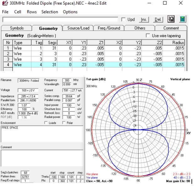
@pymekrolimus: Below is a clip showing the details of a quick study of a model based on your posts so far. The NEC4.2 engine was used for the calculations.

The results look close to what might be expected. The wire model showed no geometry or segment errors at runtime, and the AGT test returned a result of "perfect."

The wire table is shown, should you want to experiment with this model definition. The source is placed on Segment 16 of Wire(Tag) 4.

enter image description here

$\endgroup$
2
$\begingroup$

Good simulation work - your results look pretty realistic.

A note about patterns - when you talk about Azimuth and Elevation patterns, with the antenna lying on its side, it's not completely clear which they are. Normally a folded dipole is installed standing up, so it's omnidirectional. In your model there are two elevation patterns: one at $\phi=0$ (the XZ plane cut) which is what we'd normally call the azimuth pattern, and one at $\phi=90$ (the XY plane cut) which is the classic elevation pattern. It's usually obvious from the graph which is which, but not from the descriptions.

How can I verify this model? The pattern and peak gain is very similar to the standard dipole. Are there any limitations due to NEC?

NEC has lots of limitations... first respect the design rules, that helps. Then you can do some sanity checks: Are the results similar when you change segmentation? Are they smooth over frequency? Finally NEC can do an integrated total power check - this tells you if the current in the feed segment is accurate, and gives a clue about the overall accuracy.

Is the purpose of using 1 voltage source on each of the larger sides is to ensure to current is identical in each?

As you've found in Balanis - the purpose of two sources is to allow you to separate and investigate the superimposed antenna and transmission line modes. One is just a (thicker) dipole $r_{eff}=\sqrt{as} $, the other is just a pair of short-circuit transmission lines.

Does a similar derivation exist for a folded dipole, taking into account the separation length?

For a thin folded dipole, the gain should be the same as an equivalent dipole. If you're getting more than this, remember that your dipole is a bit longer than resonance, so its gain is still going up (remember NEC gain doesn't include mismatch). A rule of thumb for me is that the total circumference should be included, i.e. its effective length is $l+s$.

If I feed from the $−x$ direction as shown in Balanis, my front lobe is smaller than my back lobe. Why is this the case?

It's hard to analyse the whole structure in your head. Quite likely it's because you are on the long side of resonance - frequency too high. Try simulating it from 250-320 MHz and see how the pattern changes over frequency.

$\endgroup$

You must log in to answer this question.

Not the answer you're looking for? Browse other questions tagged .