3
$\begingroup$

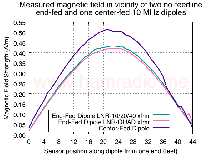
Using a sensor and procedure discussed in my article, I made the following plot comparing the magnetic field strength along a 30m-band half-wave dipole fed at center and one end.

Measured magnetic field in vicinity of no-feedline end-fed and center-fed 10 MHz dipoles.

Key points include:

  • No feed lines (just a small transmitter WiFi controlled)
  • No wires to magnetic sensor (WiFi controlled)
  • Center-fed has direct connection while the two end-fed variations have a transformer
  • VSWR presented to transmitter is 1.5 or less
  • Just a dipole hanging in free space (or as close as I could get for this test)

More questions

Have I proven one can feed a dipole from its end without need for something to electrically "push against" such as a strategic counterpoise wire or the usual feedline? Or, as quite a few reviewers suggest, is the capacitive coupling to ground still a large player in making the end-fed case work?

I ask because I plan on repeating the experiment with the antenna much further away from ground to confirm what I think I'm seeing in the data and to ascertain the role of capacitive coupling to ground. Tips for the next test are welcome and appreciated.
$\endgroup$
1
  • $\begingroup$ Comments are not for extended discussion; this conversation has been moved to chat. $\endgroup$
    – Kevin Reid AG6YO
    Commented Aug 30, 2019 at 0:11

1 Answer 1

2
$\begingroup$

It looks to be a well done experiment. We see a sinusoidal current distribution in either case, and the current tapers off to (approximately) zero at the ends. But this is what we'd expect of any standing wave on a wire of this length. Where its fed doesn't matter.

The problem with end-fed dipoles was never that they are impossible, but that they are impractical. As you know, the impedance of a center-fed dipole is in the neighborhood of 75 ohms. To feed such a dipole we will want a balun, with the objective of making the common-mode impedance much higher than the differential-mode impedance (75 ohms).

If we can construct a balun with an impedance of say, 4000 ohms, then considering this impedance and the differential feedpoint impedance of 75 ohms as a voltage divider we can see most of the current will go to the differential mode and very little current will remain on the feedline.

As the feedpoint moves towards the end of the half-wave the differential feedpoint impedance becomes higher. We can see this in your experiment with the magnetic field decreasing. As this differential impedance becomes higher, the common-mode impedance of the balun becomes relatively smaller, and thus the choking less effective.

Not impossible of course, but increasingly difficult. Of course one way to make the common mode impedance extremely high is to eliminate the feedline, as you've done in your experiment. Or one can simply accept the increased common mode current.

If your objective is to experimentally explore the consequences of an end-fed design, I'd suggest repeating the experiment with a "feedline" added to the feedpoint. The feedline can be a simple piece of wire, and you can include a current transformer on it to measure the common-mode current on it. Repeat the experiment with different feedline lengths (I suspect a quarter wavelength is especially interesting), and with and without a balun, and compare the results.

$\endgroup$
1
  • $\begingroup$ Thanks Phil. Indeed I have explored the feedline effects in simulations, hamradio.me/antennas/of-end-feds-and-feed-lines.html, and plan to, as you suggest, confirm these results experimentally with the same setup. $\endgroup$
    – JSH
    Commented Aug 29, 2019 at 20:44

You must log in to answer this question.

Not the answer you're looking for? Browse other questions tagged .