5
$\begingroup$

Can anybody provide me with an idealised formula that describes the radiation pattern of an omnidirectional dipole antenna?

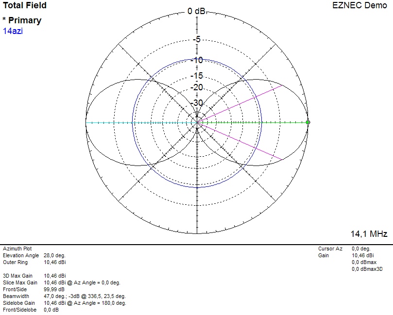
In particular I am interested in the formula that creates a plot similar to the following:

enter image description here

Note: I am looking for a simplified closed-form equation, not a full field simulation.
$\endgroup$
1
  • 2
    $\begingroup$ The polar pattern in the OP reports 10.46 dBi "gain," which is much higher than the 2.15 dBi directivity of a center-fed, 1/2-wave dipole in free space. $\endgroup$ Commented Oct 24, 2018 at 23:14

1 Answer 1

7
$\begingroup$

The antenna you describe is "omnidirectional" only in the xy-plane; it has zero radiation along the z-axis. Thus, your dipole is mounted vertically; i.e., x=0 and y=0 for all segments.

According to Antennas by John Kraus, the far E-field for a center-fed $\lambda/2$ dipole in free space is:

$$E = \frac{\cos\left({\pi\over 2}\cos\theta\right)}{\sin\theta}$$

In the case of a vertically mounted antenna, $\theta$=0 at the horizon of the plot.

$\endgroup$
4
  • 2
    $\begingroup$ You might add that power, as plotted by EZNEC, is proportional to the square of the E-field. $\endgroup$ Commented Oct 25, 2018 at 12:11
  • $\begingroup$ If the OP really is interested in the equation to calculate the polar pattern included there — that would not be the Kraus equation shown in the answer, to date. $\endgroup$ Commented Oct 25, 2018 at 12:48
  • 1
    $\begingroup$ Dick, please enlighten us with the correct equation. $\endgroup$
    – Brian K1LI
    Commented Oct 25, 2018 at 14:37
  • 1
    $\begingroup$ That would require an accurate definition of the radiator/array to which that pattern applies, which was not provided. $\endgroup$ Commented Oct 25, 2018 at 16:59

You must log in to answer this question.

Not the answer you're looking for? Browse other questions tagged .